Did I make an entire soldering station myself? really?. No, I just made the controller, the iron has to be obtained separately. Though this controller
is made to be used with Weller PES51 pencil , the idea and the circuit can be used for any pencil with minor modification in the circuit and
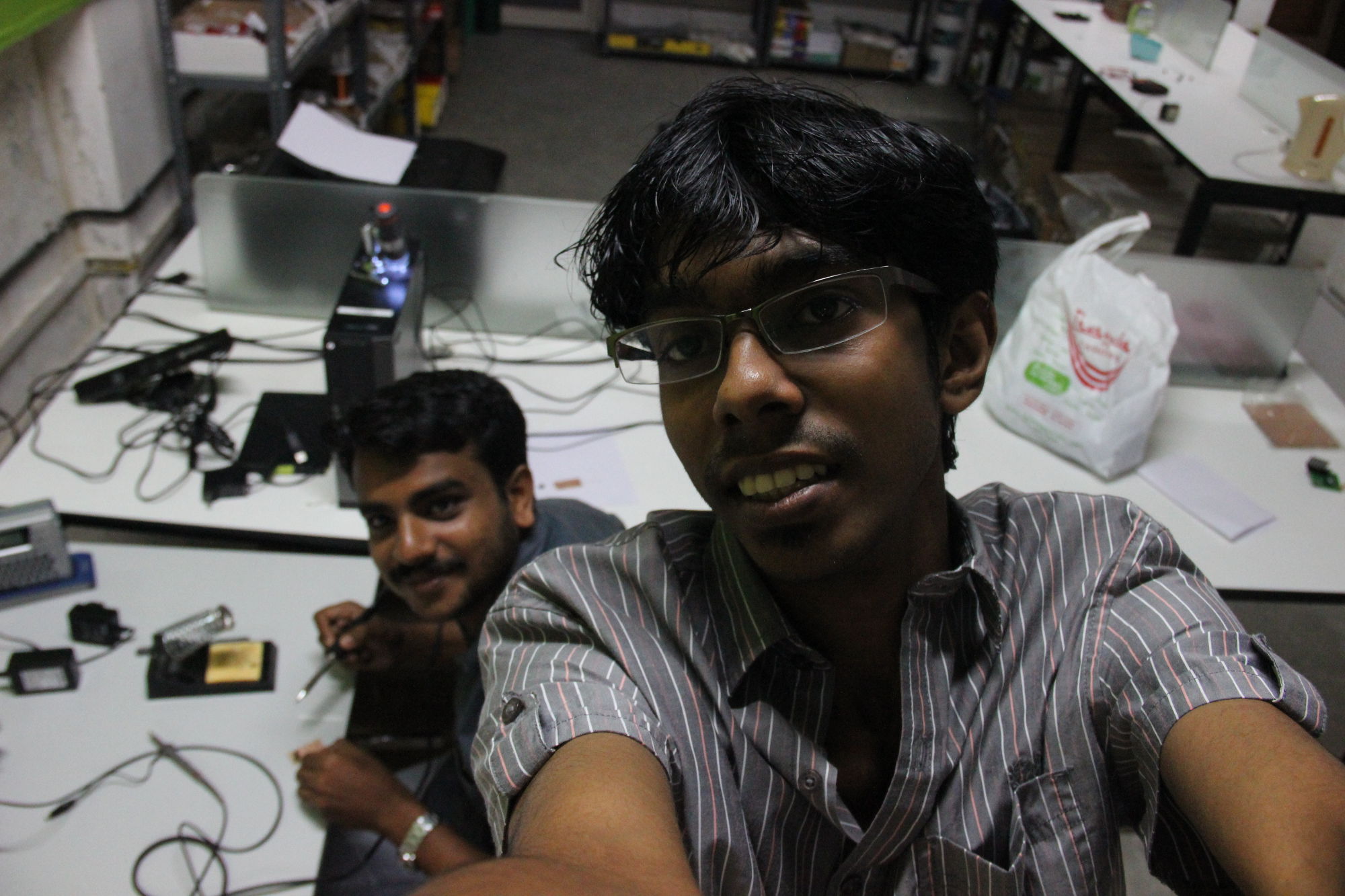
firmware, be it Weller, Hakko, Goot etc. And most importantly, I was not alone, I had help from my friend and fellow trainee (at Pre Fab Academy),
Yadu, he did most the micro-controller interfacing and coding, like LCD interfacing. Though
I started it as a solo project, later we decided to to do it together.
Okay now let's read about the development.
TODO
- Implement P/PD control code.
- Implemnt a way to set the temperature and change calibration settings via 3 button control panel.
- Design and print/make an housing.
- Power supply: find/make a 24 V power supply
- Proper calibration
Motive
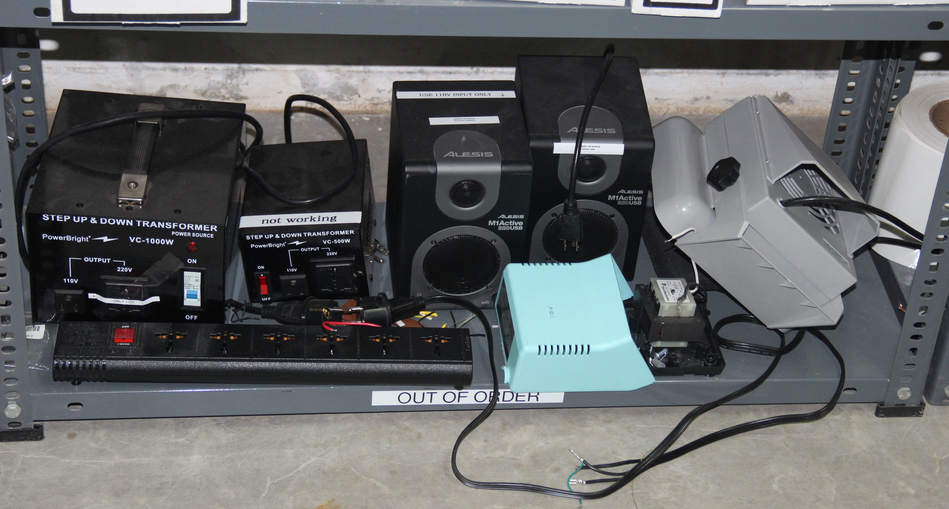
First of all thanks to whoever selected and sent the the equipments to the FabLab here. He/she was the reason for this project, why? In India we have 230v
and almost all the equipments here works on 110v. Most of these machine (including a 2KW electric furnace) require a transformer to convert the
230v to 100v. Though there is a 'big' sticker pasted on almost all equipments saying that it need 110v AC, some 'illiterate' 'idiot' will come
and plug something to the 230v supply, and BHOOOM, he just contributed something to this pile of crap.
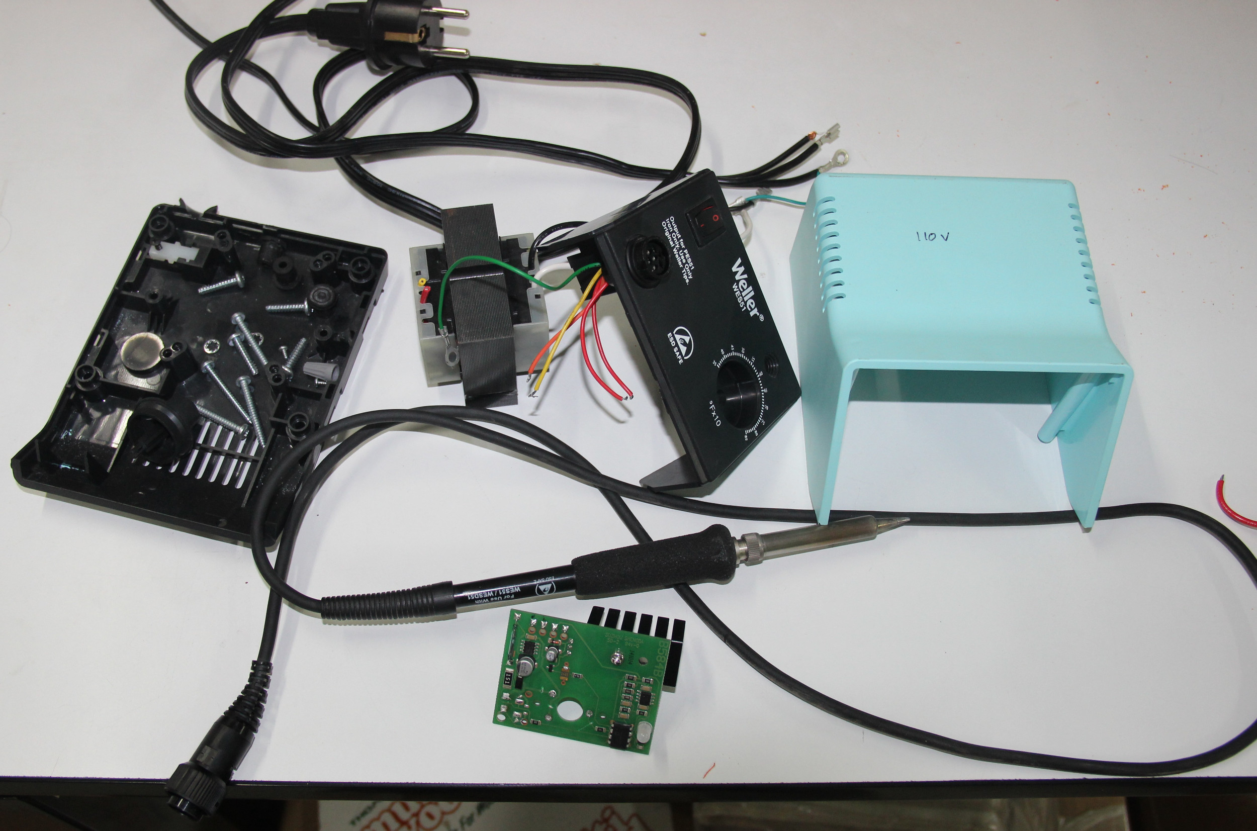
So one day in the Fab Academy we had to make the FabISP and one of the two soldering
station is not working. My friend Yadu told me that he saw someone plugging it into the 230v wall
socket. So we were almost sure that it got fried, so me, Yadu and our trainer Mr Luciano tried opened the controller unit expecting a blown fuse.
To our surprise this $100 equipment didn't have fuse inside. On inspecting further we found that the transformer primary winding of the transformer
and the voltage regulator inside the circuit board is fried. The micro-controller was not getting any power even if we supply 24v to the board
directly, using a lab power supply.
Evolution
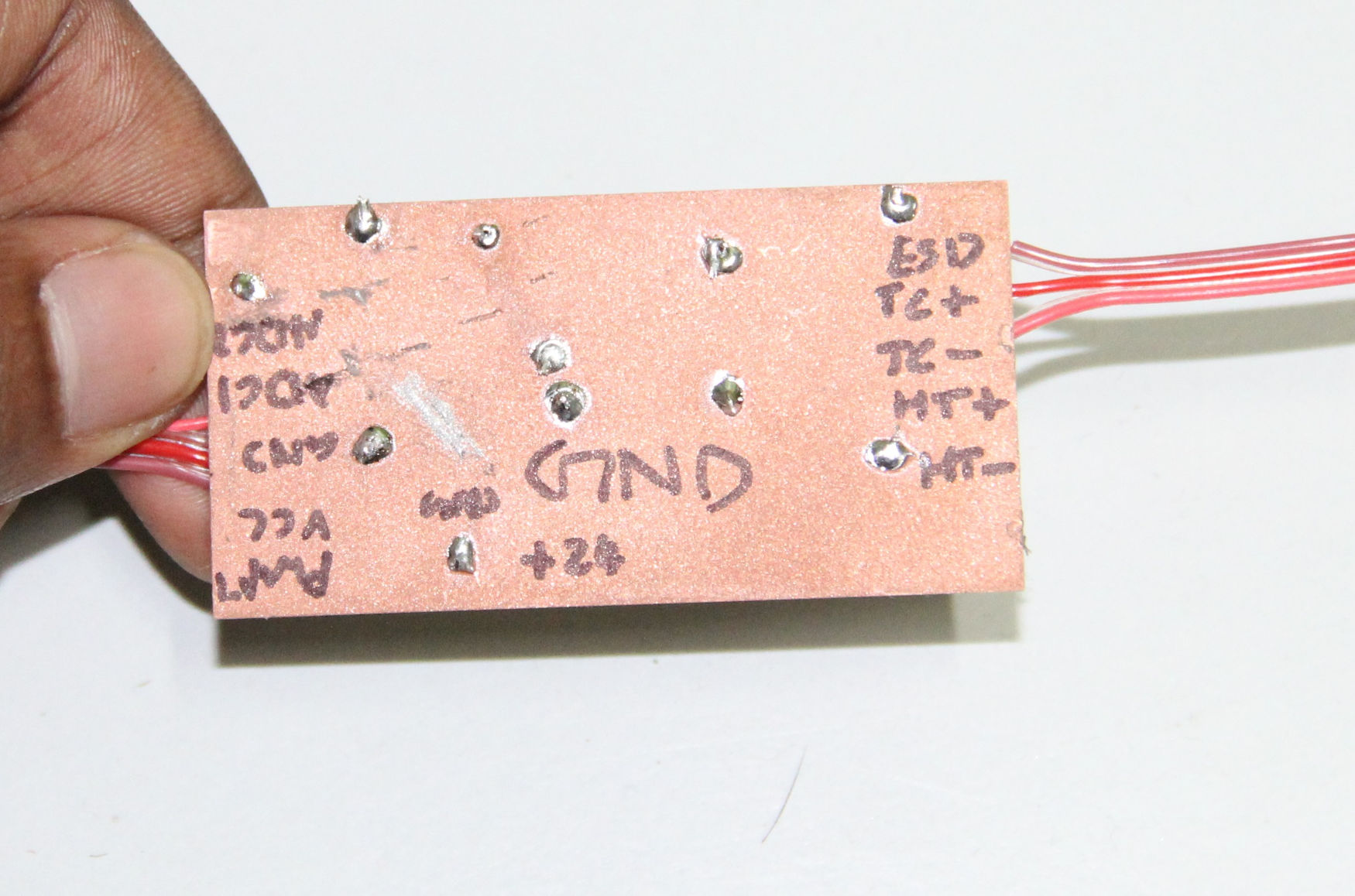
The pencil had 5 wires coming out of it, I knew that the pencil had a heating element, a temperature sensor and the pencil's rubber grip is grounded for
ESD protection.
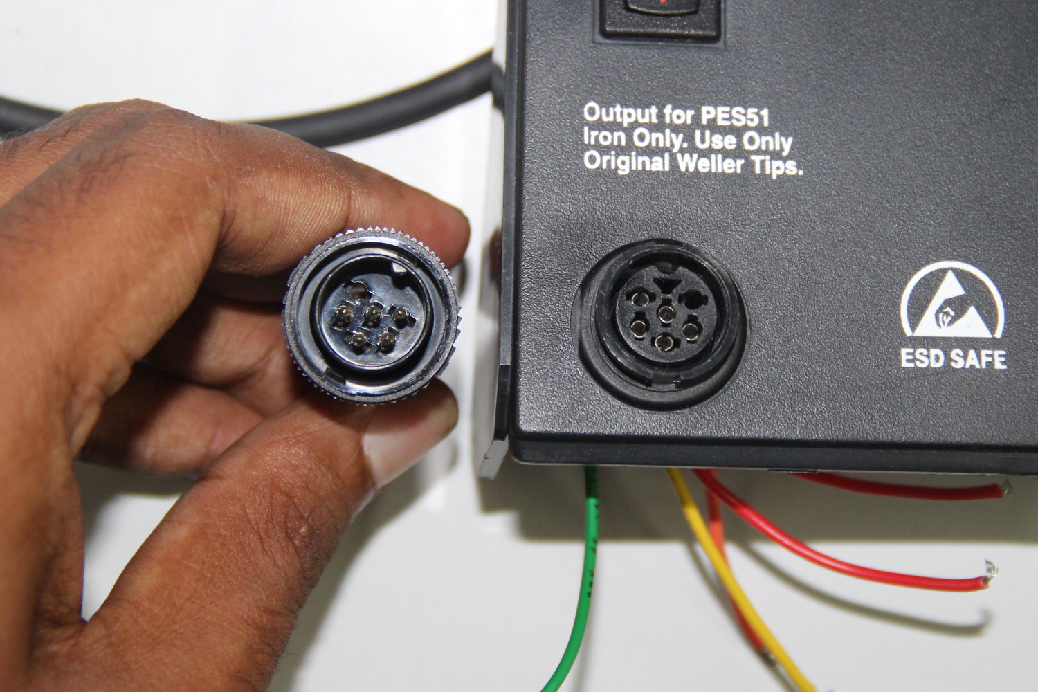
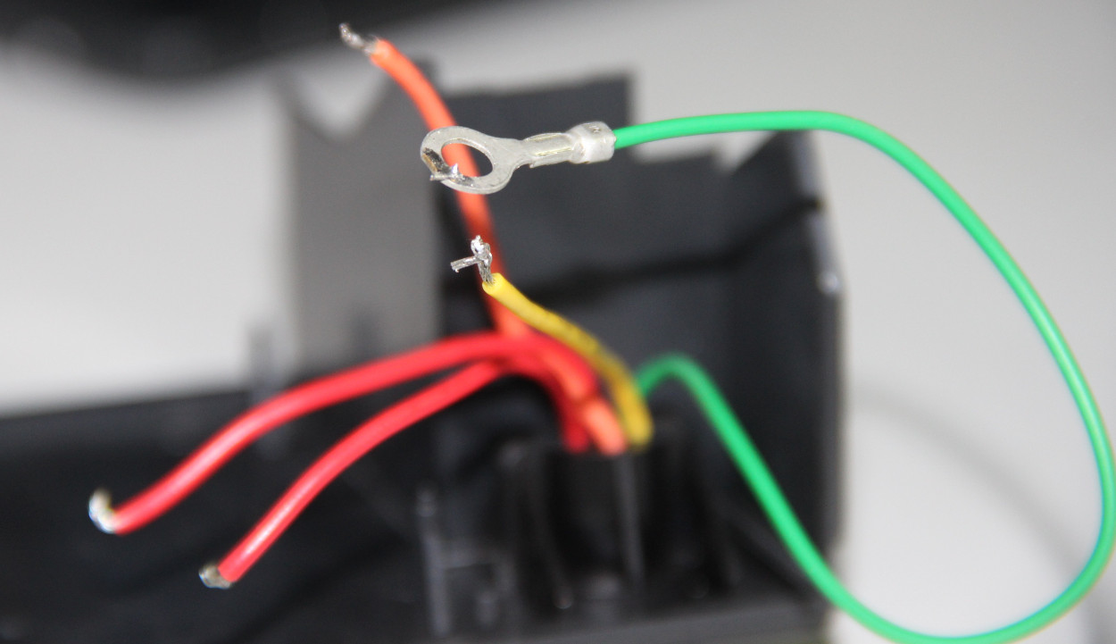
5 wires, so the guess would be, 2 for heater, 2 for sensor, and 1 for ESD(grounding). On inspecting the connections, I find that the green were is connected to the earth wire of the mains via the body of the transformer, so that wire clearly is the ESD. One down 5 more to go.
Then I inspected the circuit board and followed the traces hoping identify the wires.
I was so excited about the project, so much that I forgot to take a any pictures before removing the pot and the wires from the front-panel.
You can also see that I broke some of the traces for testing purposes. I had completely that I was supposed to document this project. So I'm
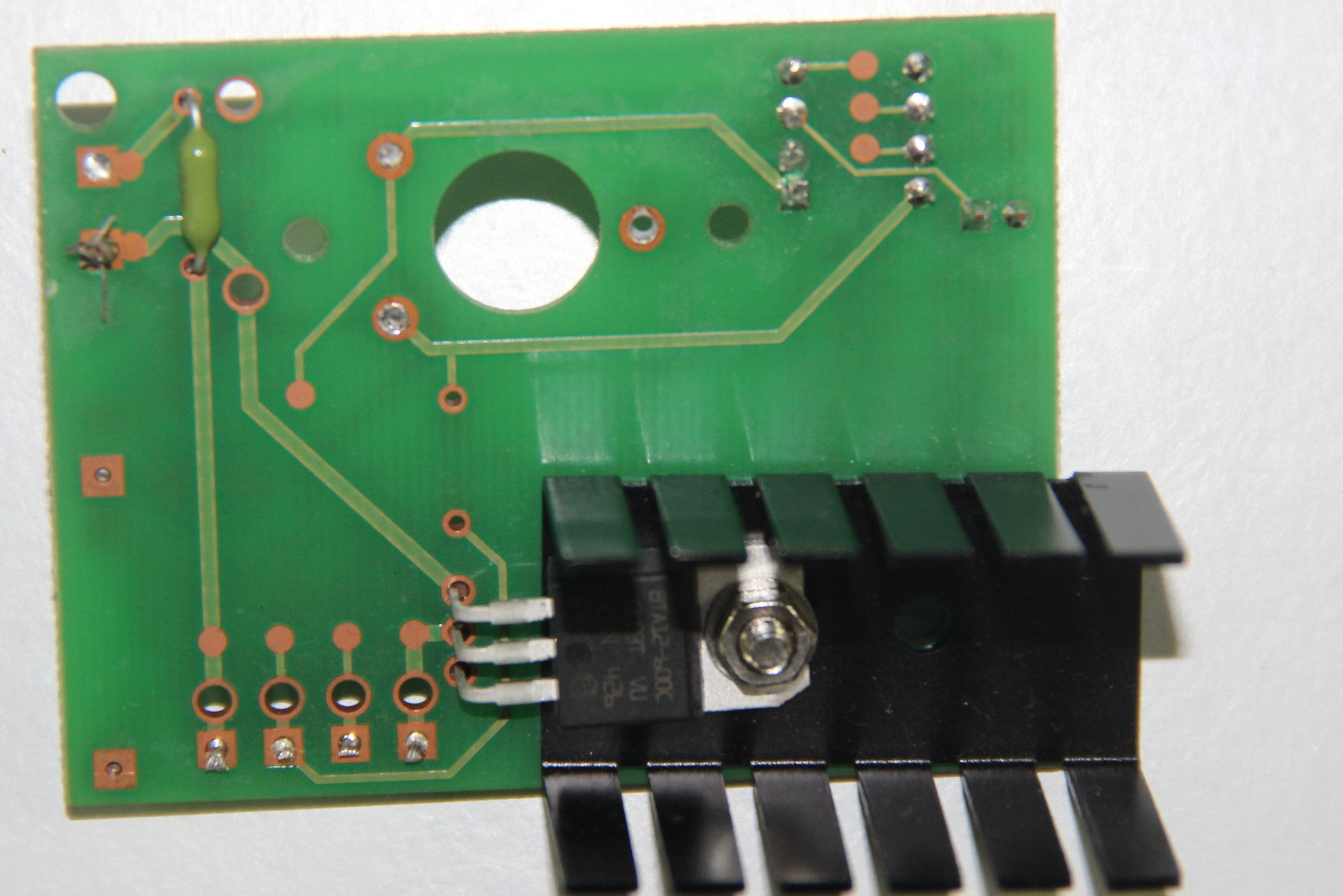
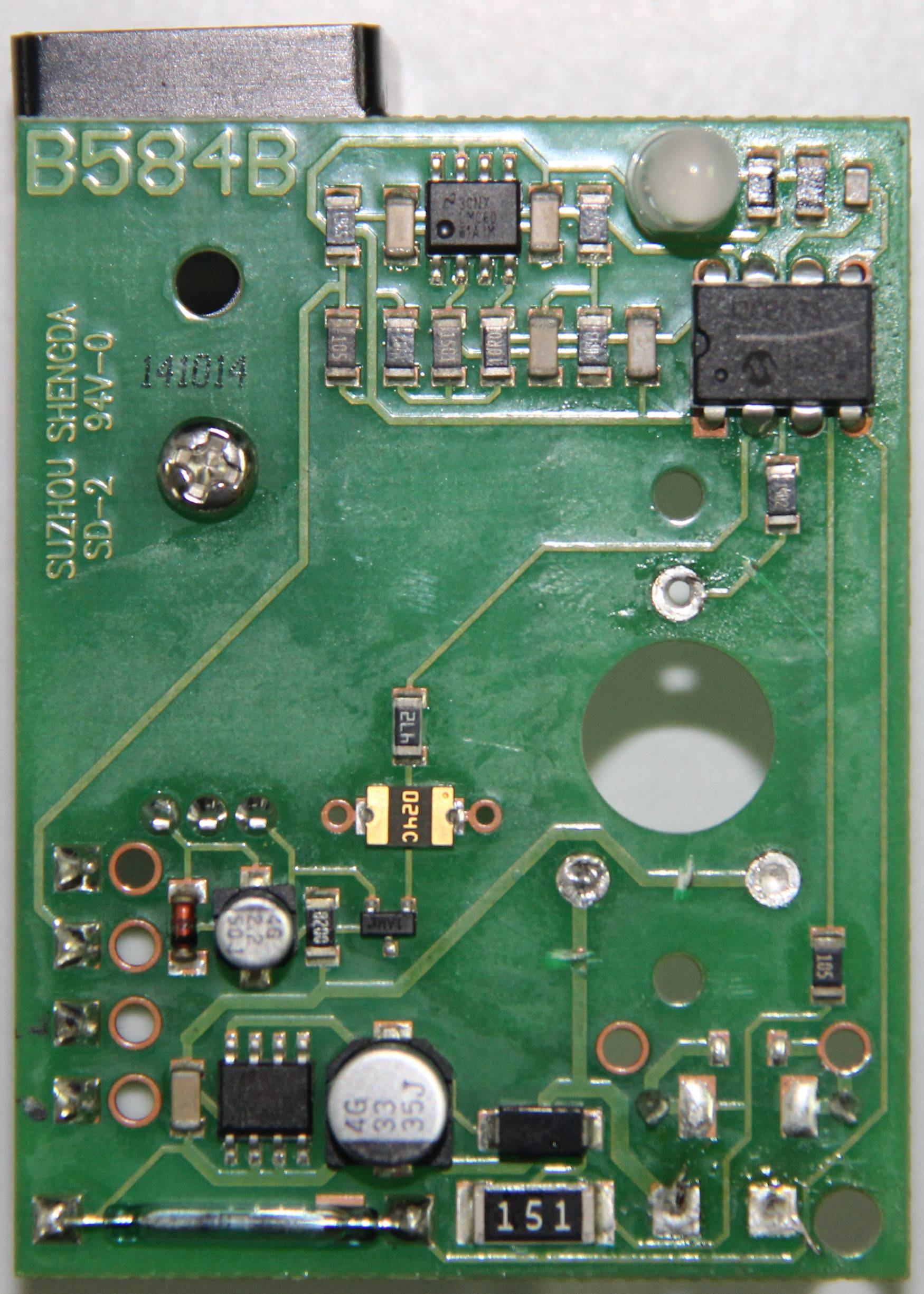
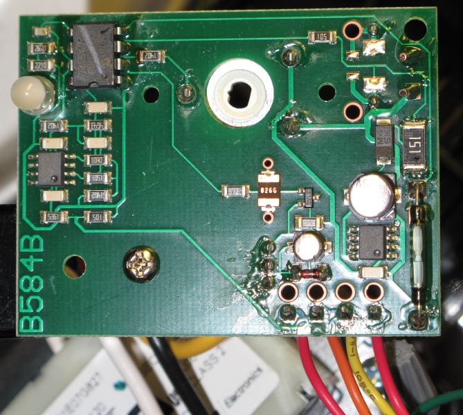
posting two pictures from this page for reference. This
guy took good quality pictures, thanks you Triden.
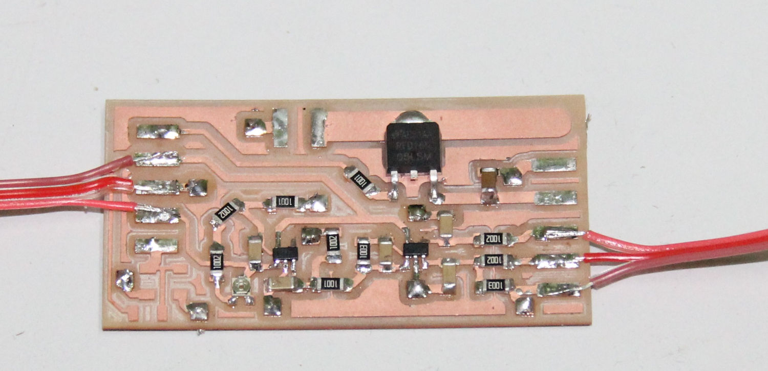
You can see that the two thick traces from the pin one and two of component with the heat sink. I will be mentioning about these soon.
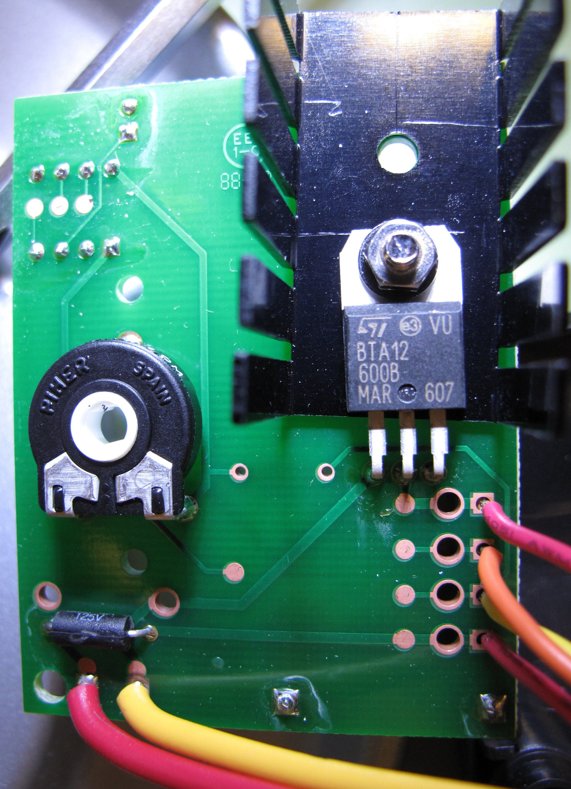
See that big component with a heat sink? It's FET or a power transistor (very likely a MOSFET) which controls the power flow to the heater.
Component is marked BTA12, and I found this data-sheet . I was wrong!
it's not a FET, not a transistor; It is a Triac, a Silicon Bidirectional Thyristor. The control circuit/micrcontroller will be controlling this
component via a PWM (Pulse Width Modulation) signals to the heater power. So?, follow the traces from the Triac, see the two thick traces from
the Triac?, from pin 1 and pin 2?, these wires must be going to the heater. Following the trace further, I found that one these traces goes to
the transformer secondary via a shunt resistor. And the other goes to one of the RED wires from the front-panel. So the other RED wire must be
the going to the second wire of the transformer secondary, right? Yes it does and the circuit is complete. So the RED wires are going to the
heater. The clues were, thick traces to carry high current (about 2A), direct connection to the 24v AC output of the transformer (no digital
component/sensor will be powered by the unregulated AC supply).
Lets be sure about it, the pencil is rated for 50W at 24v, means it draws about 2A at 24v. So the heating element must have a resistance lower
than 12 ohms, lets see.
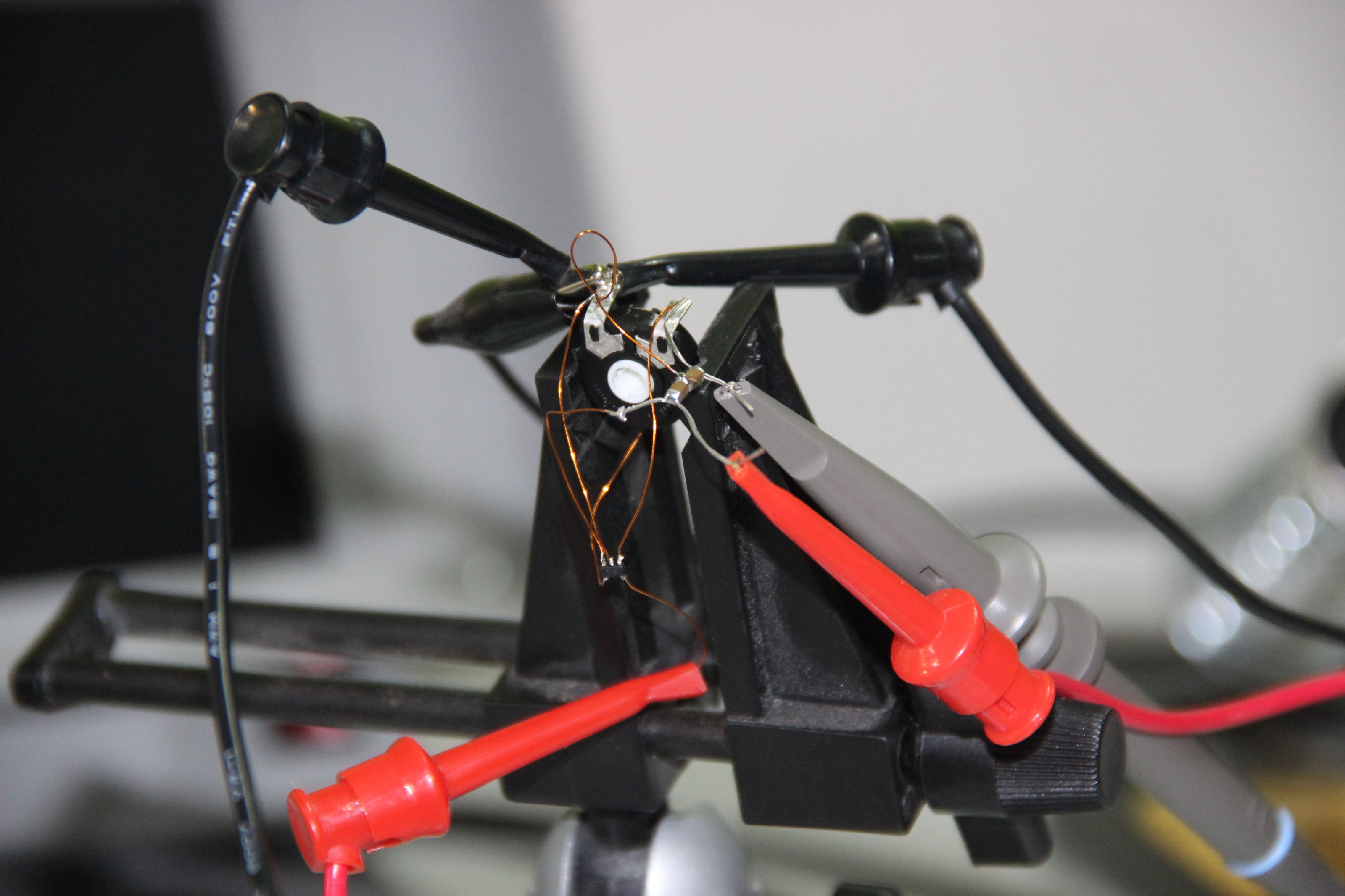
I set 10 V at a maximum current limit of 2A with the power supply and connected the supply to the RED wires. The pencil drew only 0.94 A, which
means the resistance is about 10/0.94 = 10.6 ohm. Just like we expected.
With just two wires remaining it is obvious that these are going to be the sensor leads. Now what type of a sensor is this?
If the sensor is resistive (the resistance changes with temperature), PTC, NTC, PT100 etc it must have a high resistance, ranging from 50ohm
for an RTD to 10s of Kohms for a thermistor. . And if the sensor is a thermocouple (produces a potential difference proportional to the temperature),
it must have a very low resistance. When measured I found a very low resistance, almost short circuit so it must be a thermocouple and my 'googling'
also supports this guess.
Lets check the thermocouple, the information from Wikipedia and NIST (Nationla Institute of Standards and Technology) data tells that about 4 mV potential difference can be expected across the terminals at about
(100℃ + room temperaure). (100℃ + room temperaure) because the thermocouple can only measure the temperature relatively. It is made
of a junction between two metals and the potential drop produced by the junction depends on the temperature difference between the metals. In
case of the soldering iron one of the metal is at the tip temperature and the other will be at room temperature. So the tip temperature is measured
relative to the room temperature.
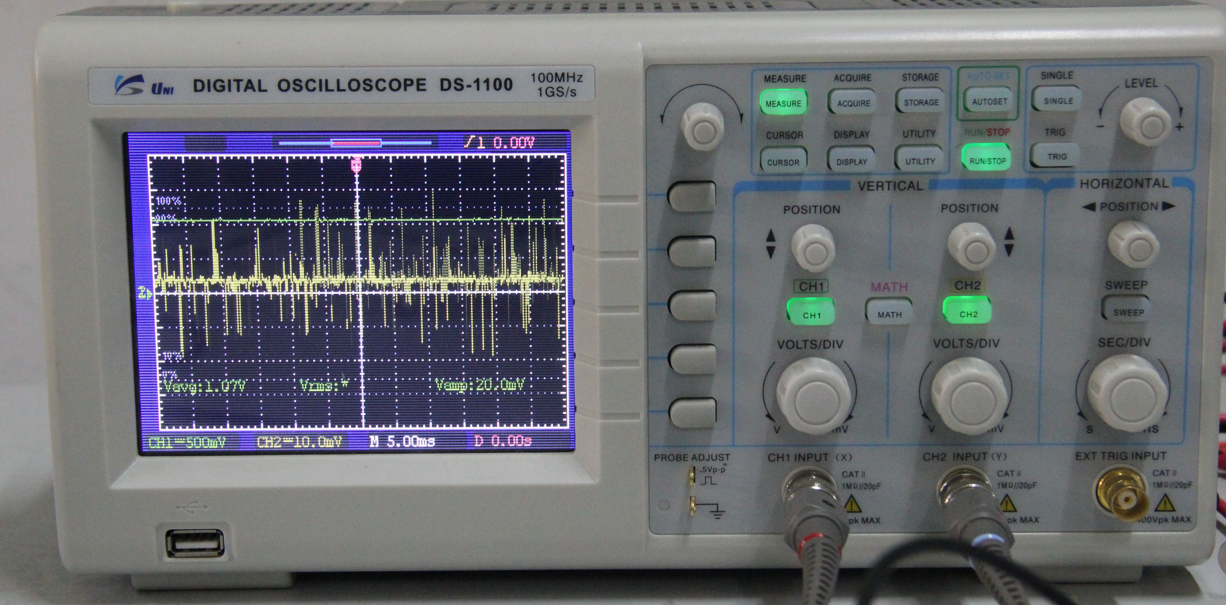
This tells us that even at the maximum temperature of the iron, the potential difference by the thermocouple will be under 20 mV.
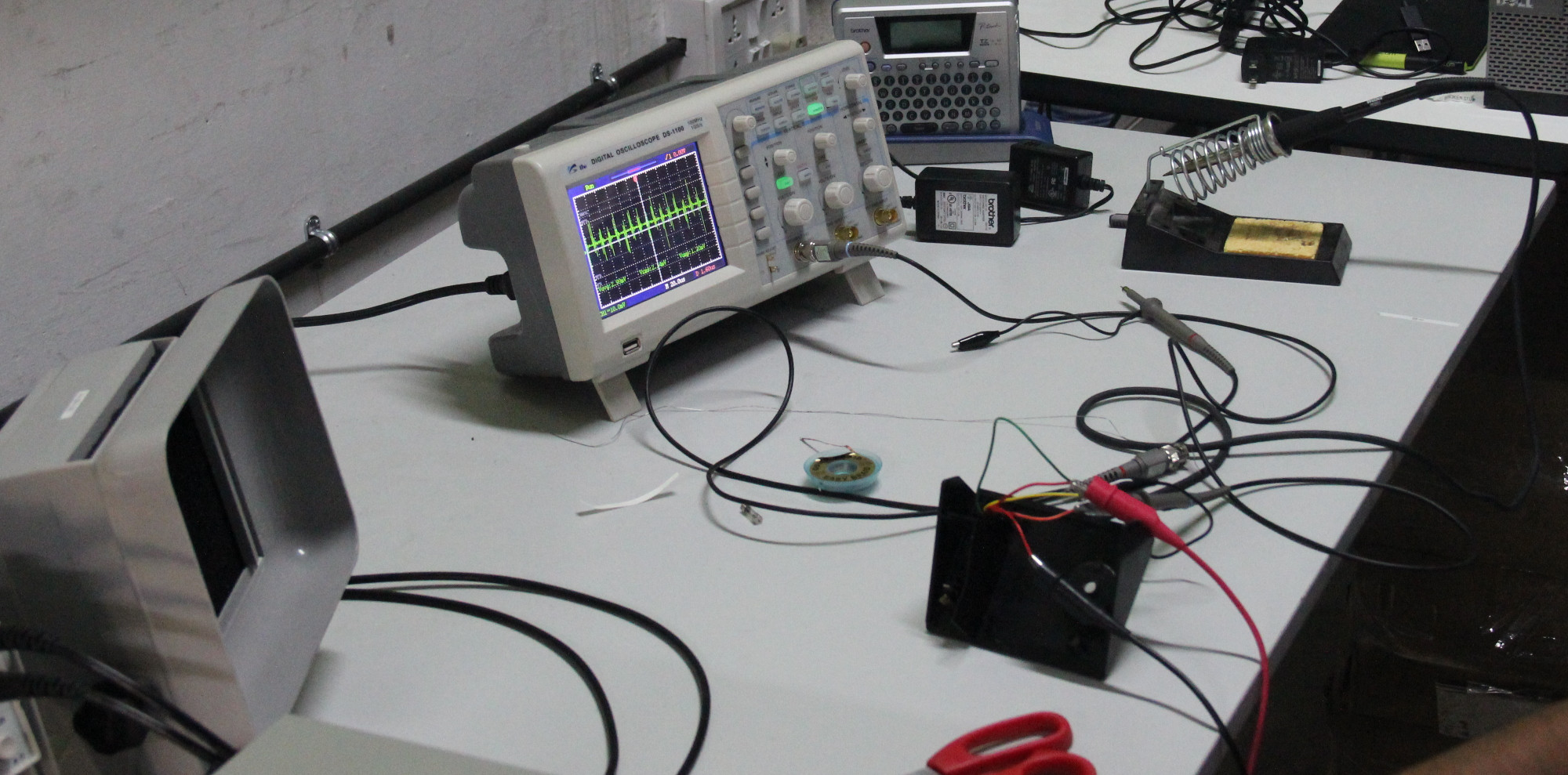
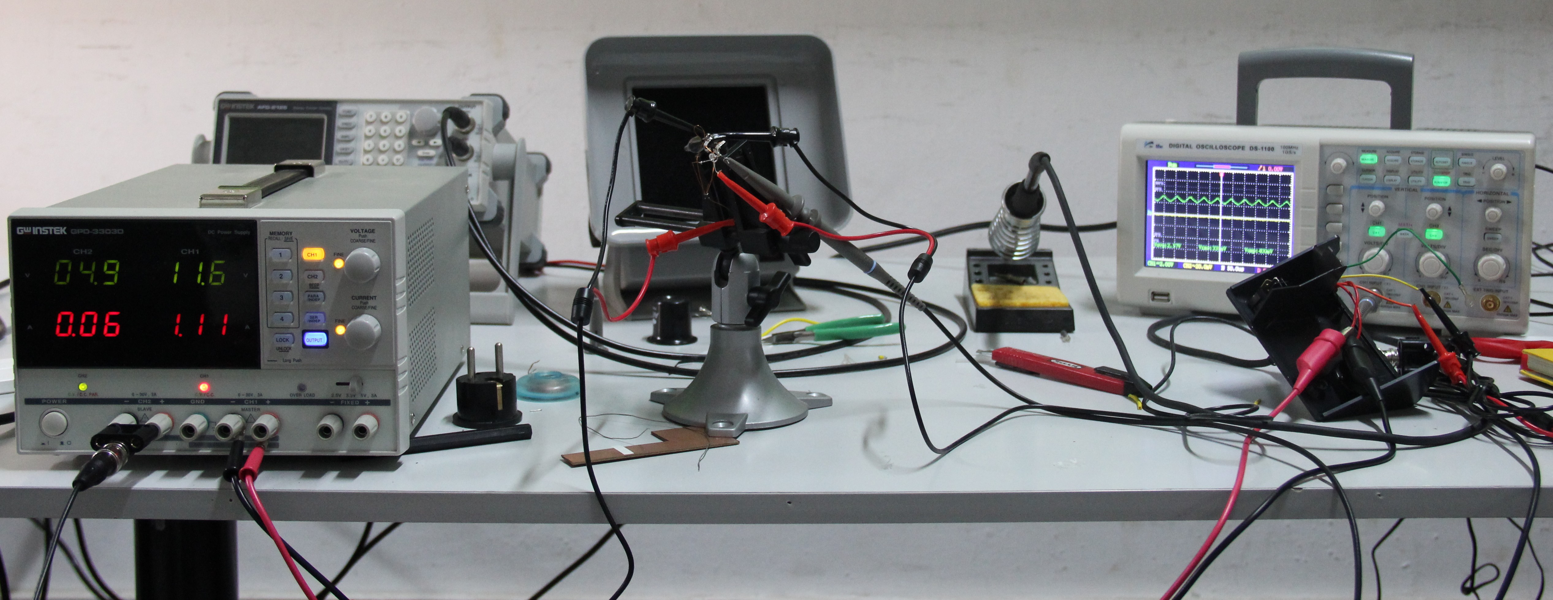
Stage one: the makeshift soldering station
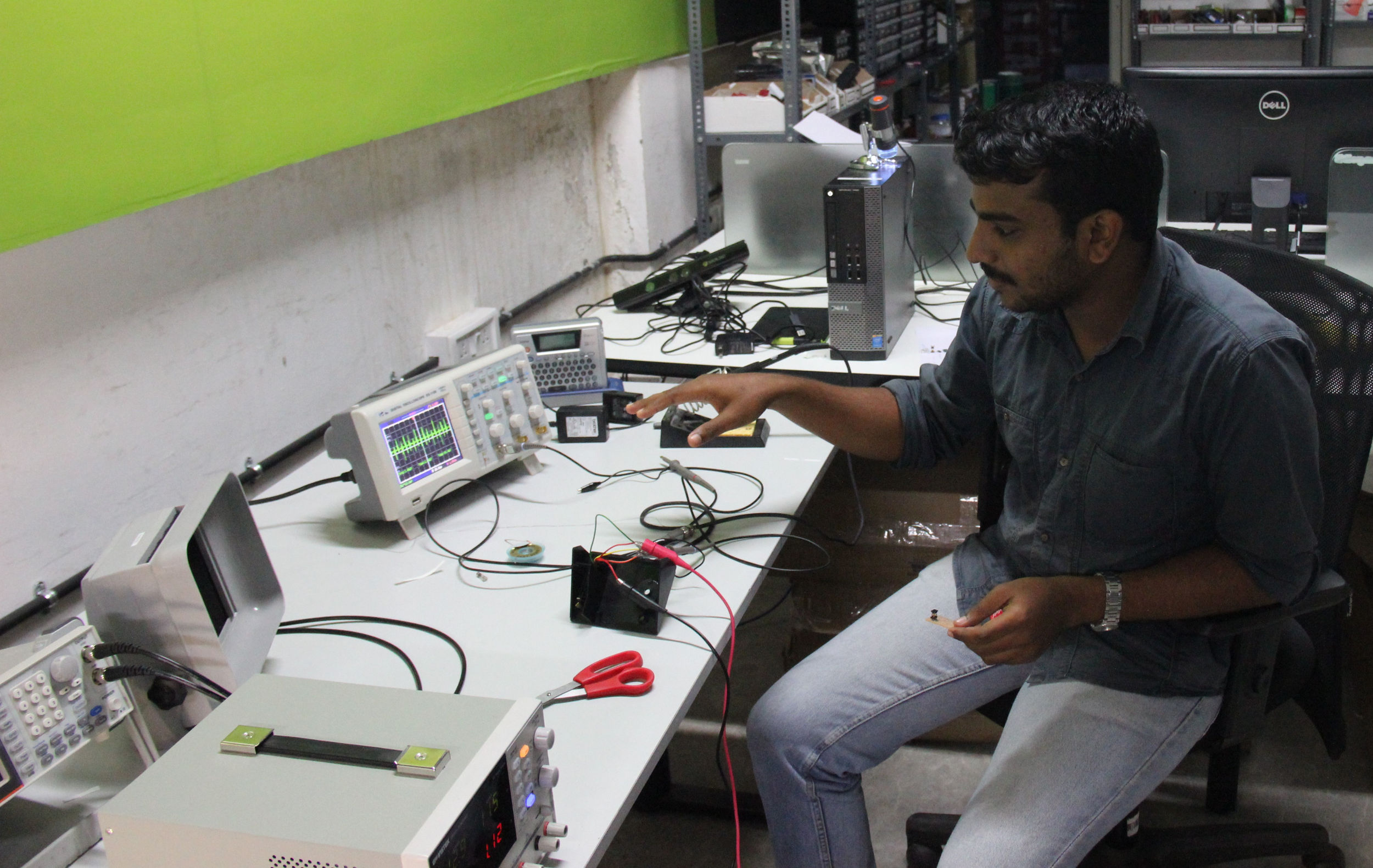
Okay, I don't have the time to make the control unit now, I need to make the FabISP.(don't runaway I'm going to make it, keep reading) So I set the power
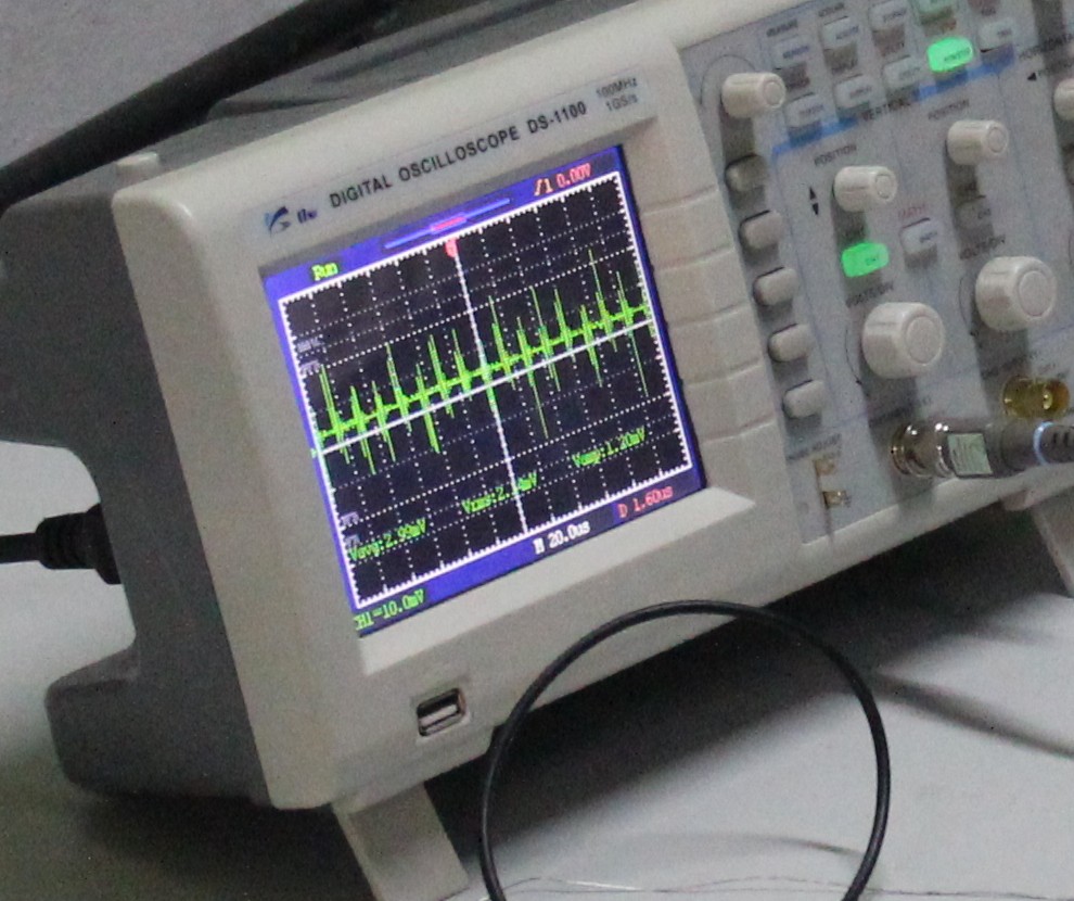
supply to a maximum of 24v and connected to the heating element (RED wires). The thermocouple is connected to the oscilloscope to monitor the
'temperature' (actually the potential differance). The DSO is set to read the average DC voltage across the thermocouple.
This one is a really expensive soldering station, but it will do for the day. Okay, now, picture time....
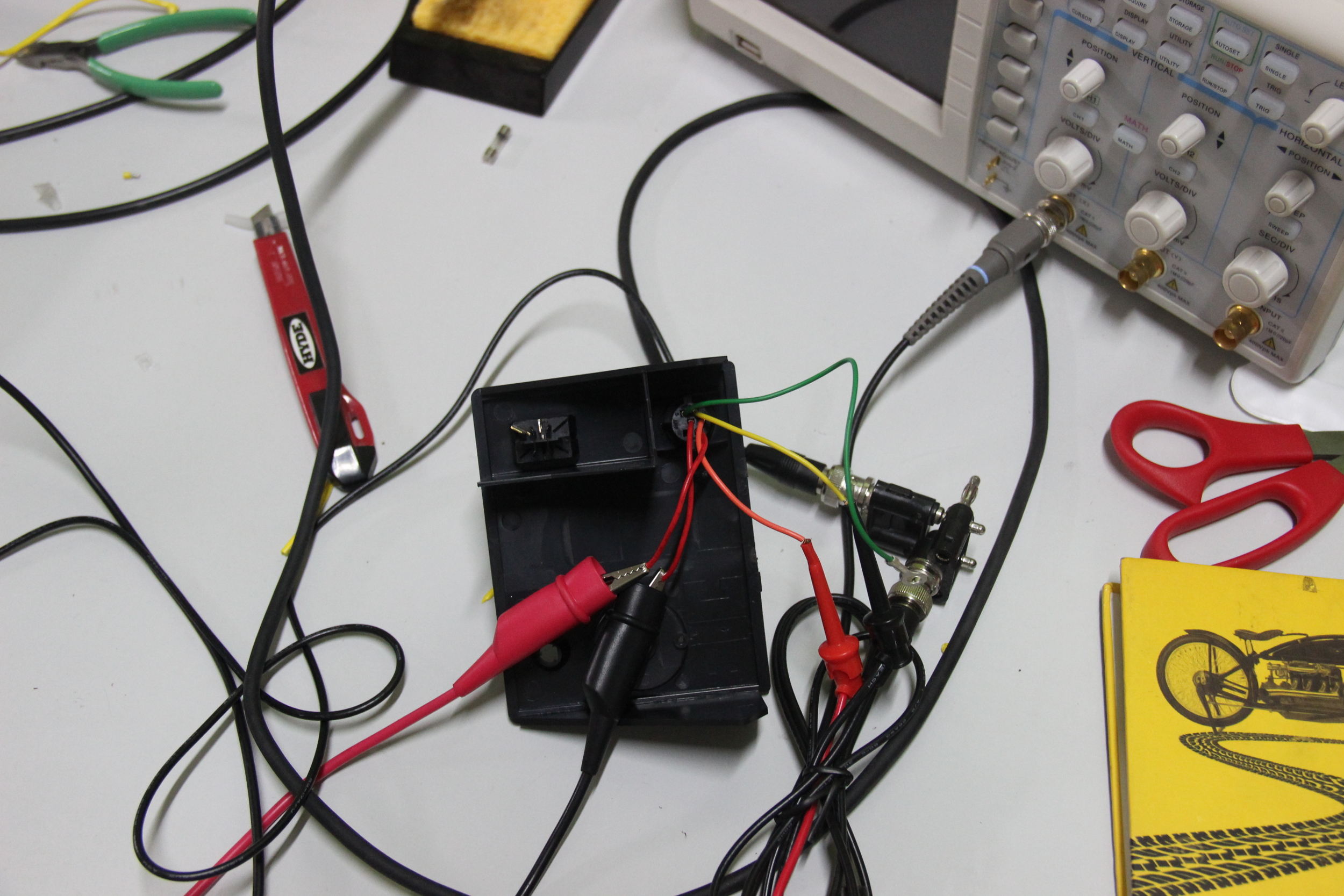
To make use of this setup we need to hold the pencil at a safe temperature and we don't know what value of the DSO reading corresponds to that temperature.
The fix? I connected the pencil to the working controller and let it heat up to the set value, disconnect and immediately connect to the socket
of our make-shift soldering station, whatever the DSO displays corresponds to the temperature we need the pencil to be at. Tweaking the current
limit dial in the power supply, I found the current required to keep the pencil at this temperature, 0.9A to 1.0A.
The setup is working and I could solder my FabISP. I also used this setup to de-solder the board later, and use the components to make another
board, FabISP Key. But the signal is too weak compared to the noise. I have
to amplify the signal.
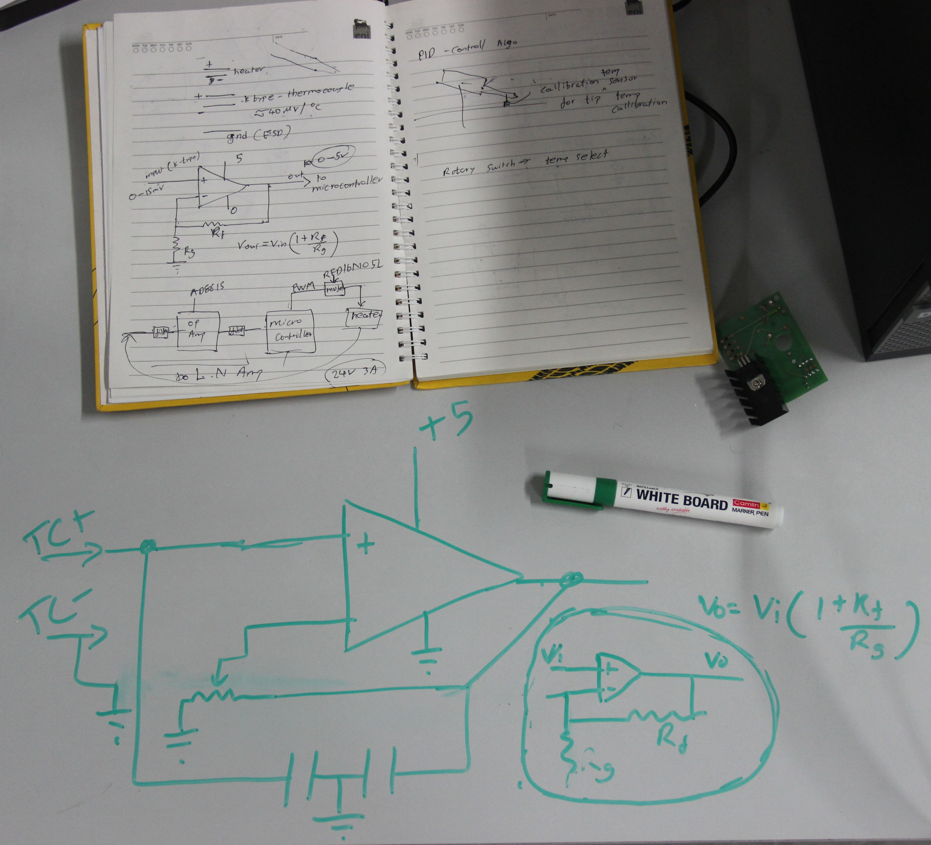
Stage 2: Op-Amp
I will be making the controller using one of the atmega micro-controller available in the lab. Most likely a Atmega168p or Atmega328p. Its pretty obvious that we have to scale (amplify) the 1-20mv to 0-5v for measuring the thermocouple potential via the ADC. This process obviously requires an amplifier, so time to make one. But one problem, the components in the FabLab are only available SMT packages. So prototyping is going to be challenging.
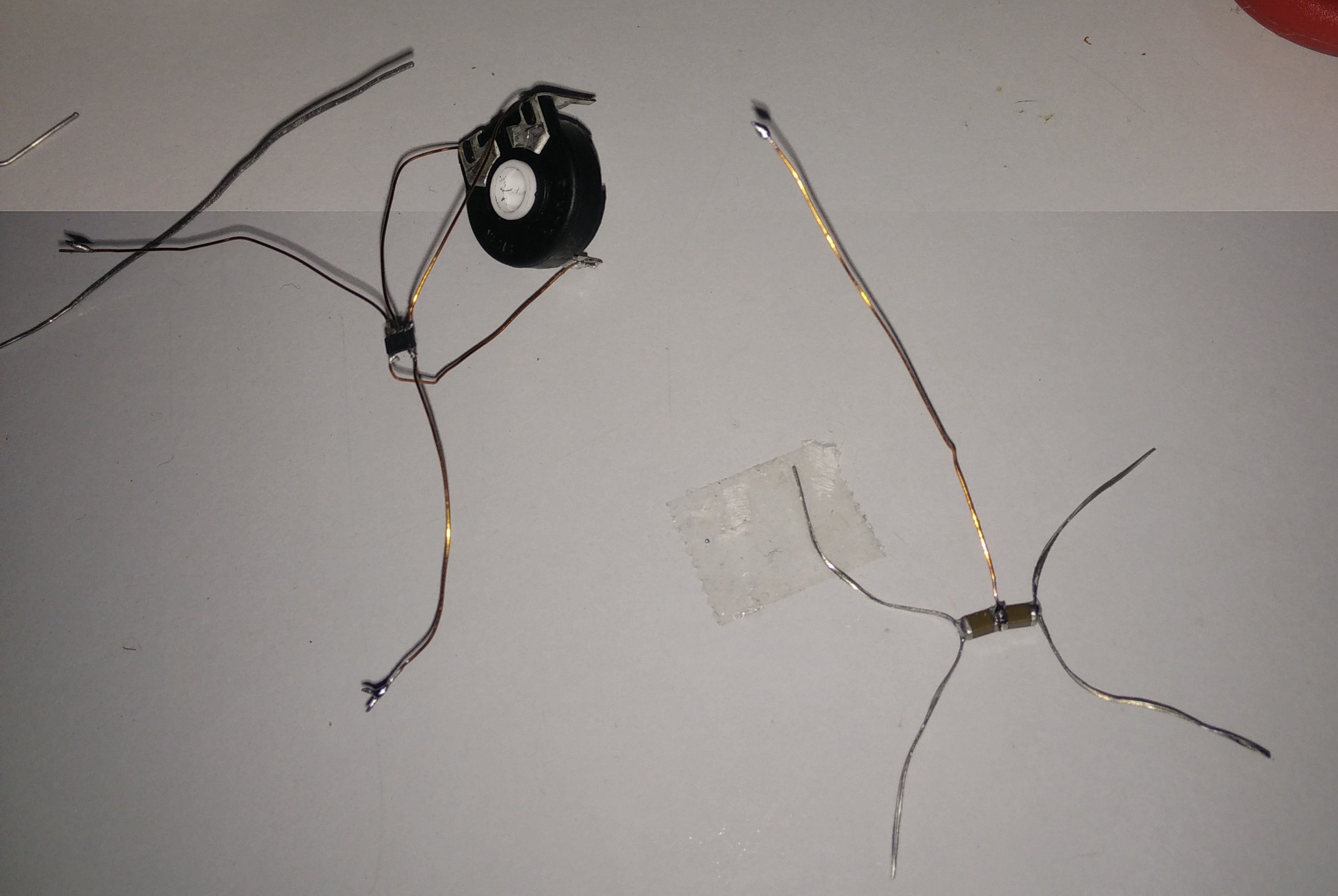
I made a simple non-inverting amplifier using the op-amp AD-8615, few filter capacitors and the potentiometer from the original Weller logic board. And
this little creature was born.
Stage 3: Op-Amp 'onboard'
Its time to take the project to the next level, time to make a proper PCB for the amplifier. I did a lot of research and came across an application note
from Microchip, link here and here.
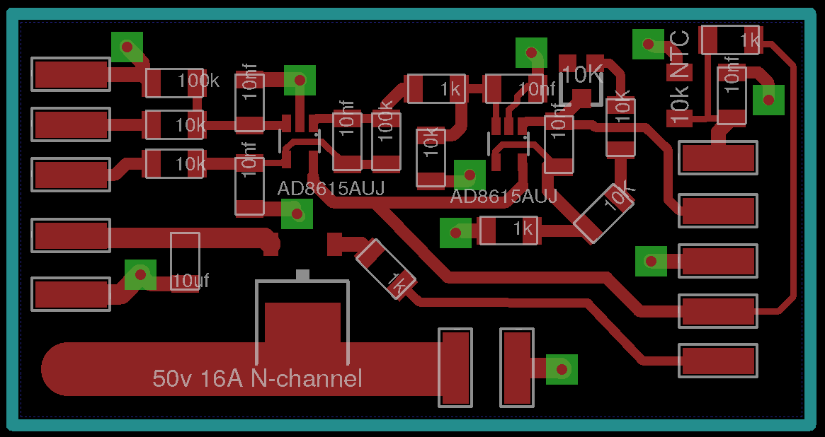
The app-note describes a differential amplifier using two op-amps to amplify the signal from a thermocouple to 0-5 V range. So I used this design
as a reference for my design. The board I designed has an amplifier setup described in the app-note, a 10K NTC temperature sensor for measuring
the absolute room temperature and the MOSFET, RFD16N05L (16A, 50V,
60W continues, logic level N-channel-MOSFET). All five wires from the pencil goes to this board. The board has two outputs for the ADC, basically
the absolute and tip temperatures. The board also requires two levels of voltage, 24v, 2A supply for the heater and 5v for everything else. I
also made a large copper pad which act as heat sink for the MOSFET. The design uses a double sided PCB and the bottom layer is used only as a
ground plane.
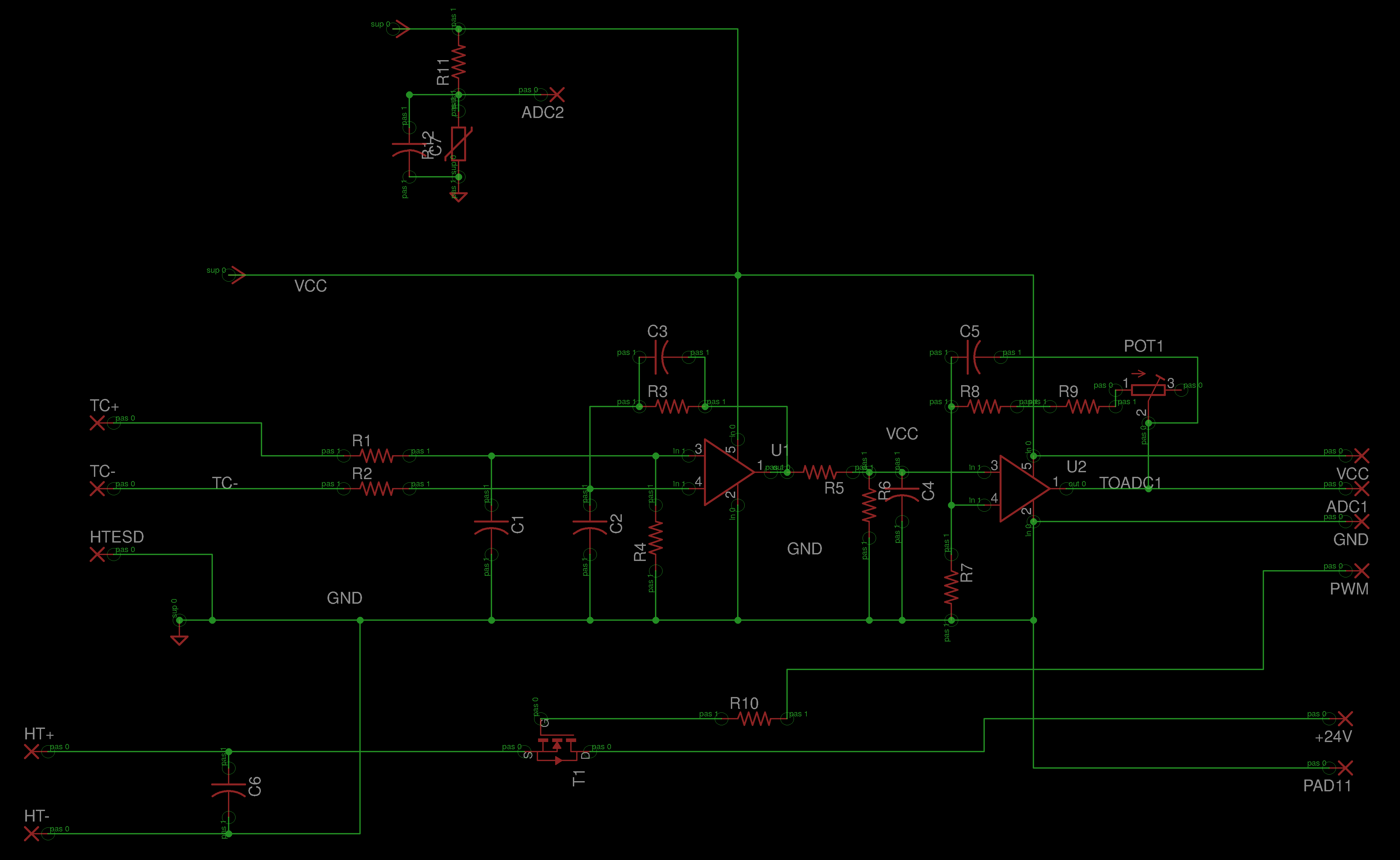
Eagle files
Schematic. Board.
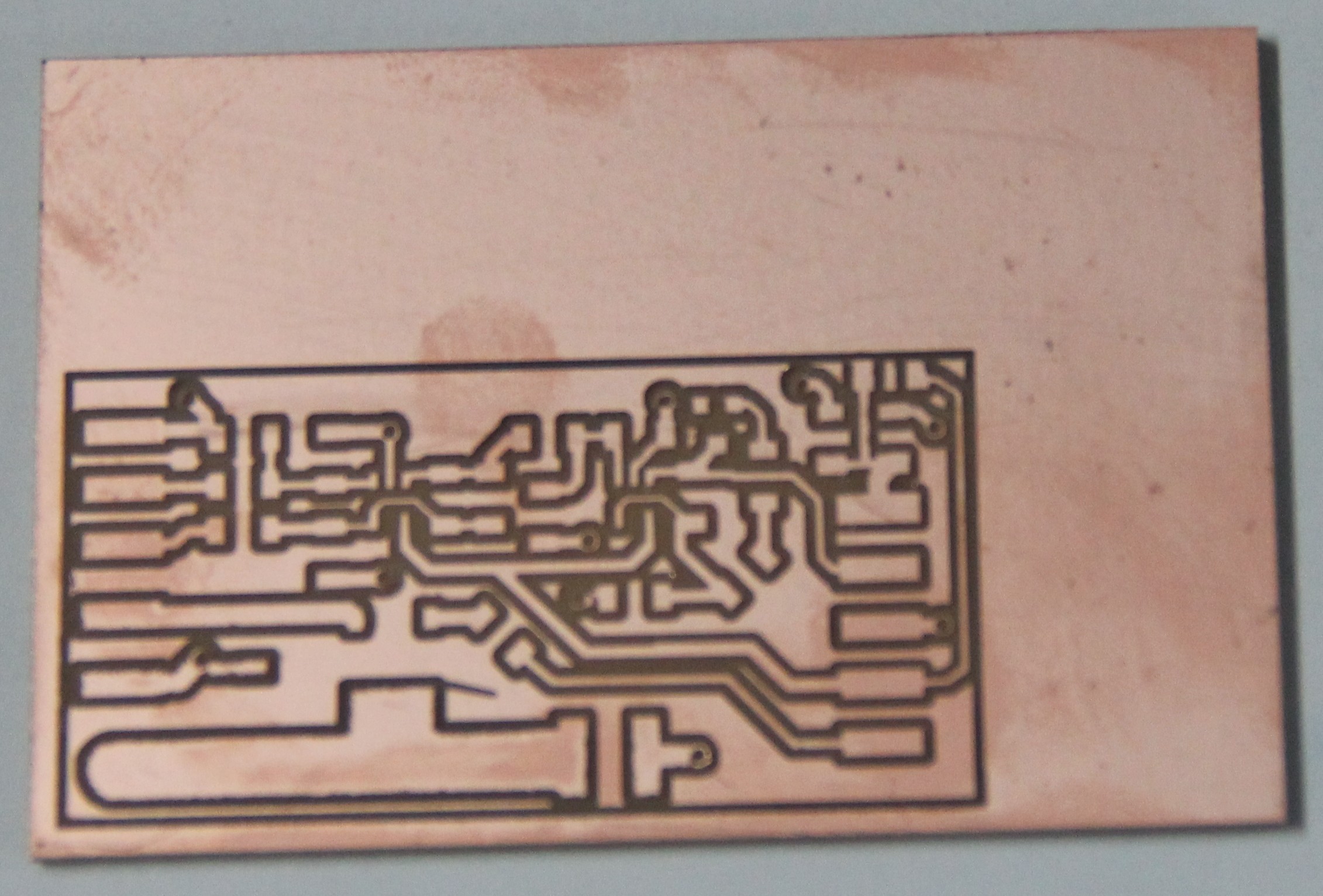
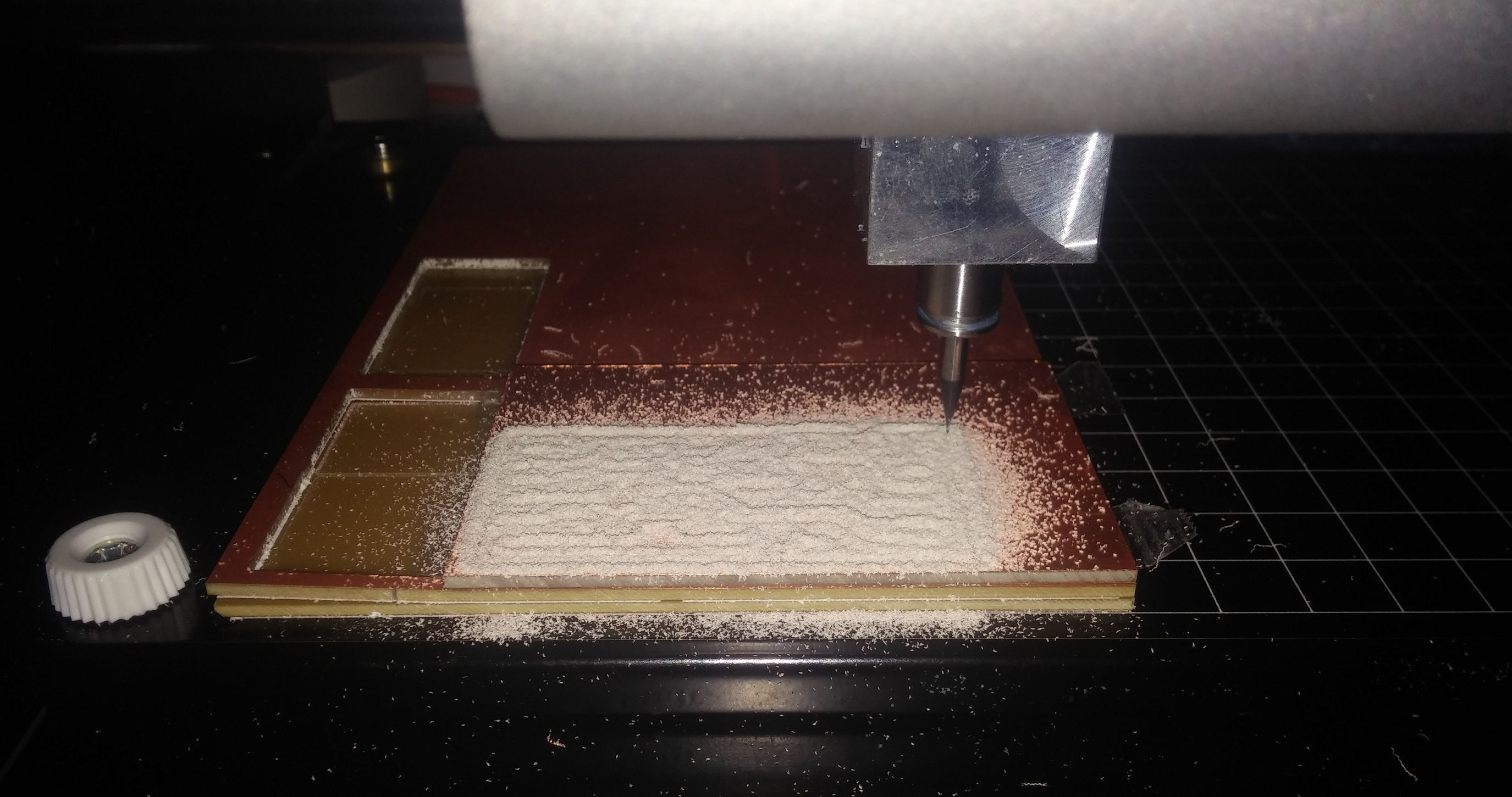
From this design we milled the board using the Roland MDX-20 mill in our lab. The image of the board (top, pads, vias and milling layers) is exported as monochrome .png and edited using Gimp to make the following images. These image were used to mill and cut the board. The fab modules are used to control the machine. Once the image is loaded and correct settings are chosen the software predicts the tool path so that the white area in the image is preserved.
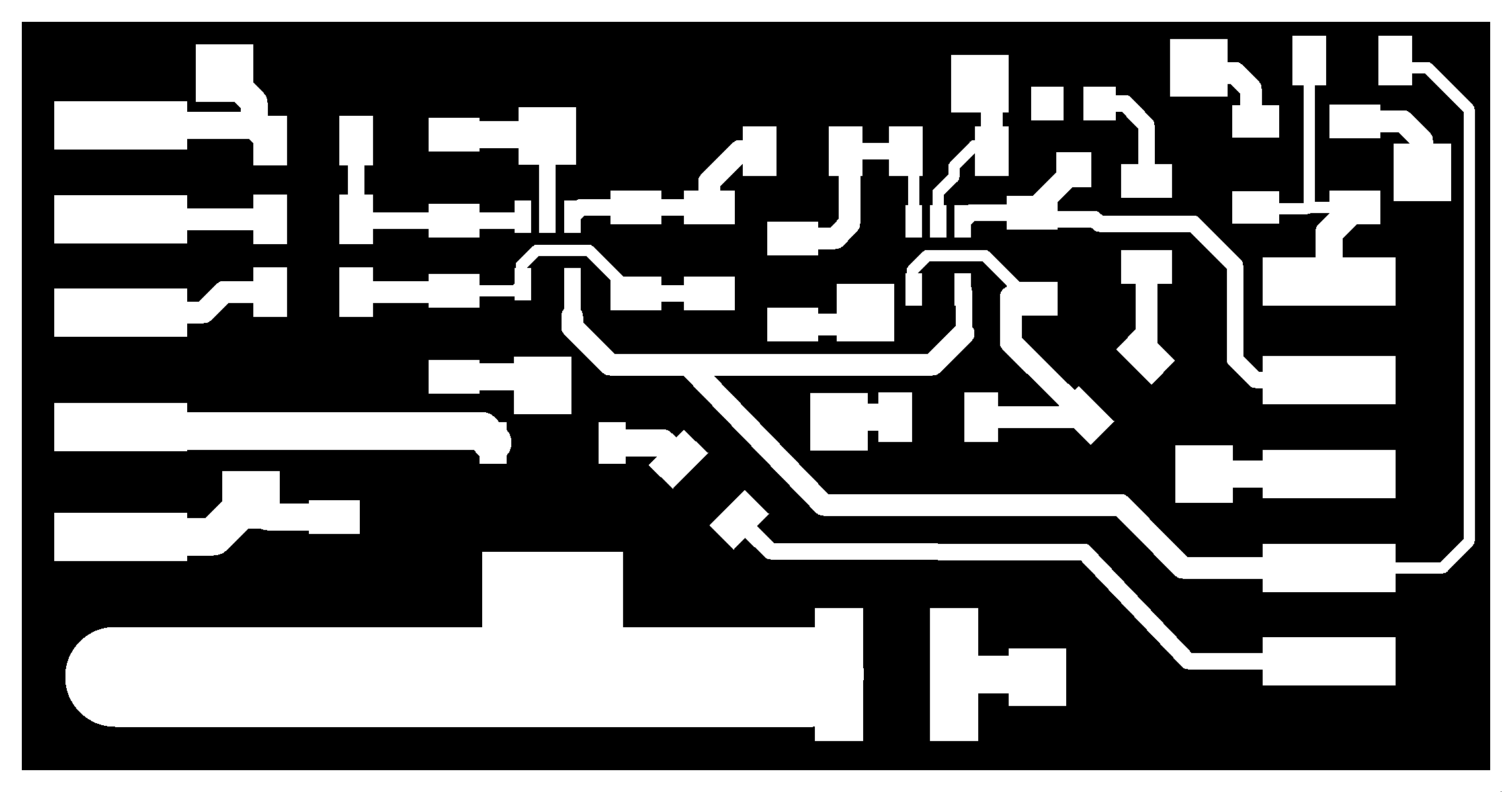

One thing to keep in mind if you are using the image files to mill the board, find out what the actual dimension of is from the .brd file in the eagle. Use this dimension to scale your image.
Few more pictures and videos.
An interesting animation of the last stages of the design, actually the routing.
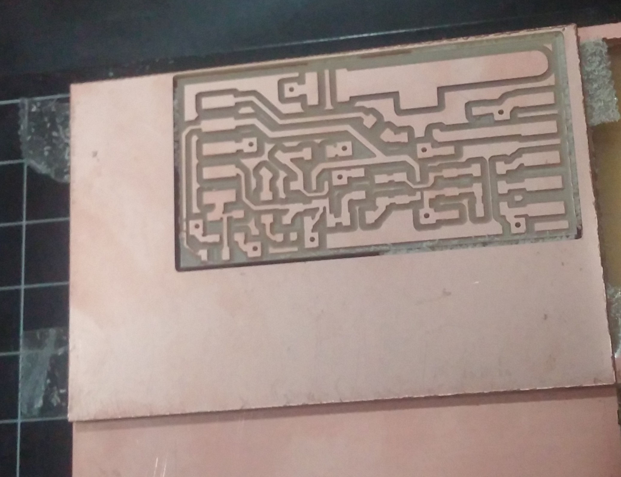
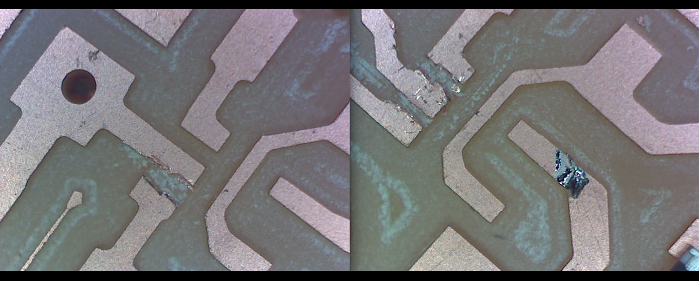
Even after the redesign there was a silly mistake, at some places the traces where too close that the milling bit didn't pass through, so they were still connected, I had to use a knife to fix it before soldering.
During this time my friend Yadu, was experimenting with interfacing the LCD to the FabDuino he made (I too made a similar board, not FabDuino, will talk about it later). He had some troubles prototyping the LCD interface; you can see
the pictures in the next section and you will know what I'm talking about. In the beginning of the Pre-Fab Academy one of our trainer Mr. Luciano
told us that every one of us should do an individual project, later because of the shortage of time and equipments, he said that we can do group
projects, thats when Yadu joined the project, actually he was helping before too, but now it's officially OUR project. So he took over the micro-controller
section, he started by interfacing the LCD and later he started working on the ADC interface and PWM control.
The FabLab or any lab, needs some basic stuff in their inventory, most importantly jumper wires, a lot of them, and all types(M-M, M-F, F-F).
Anyway it's time to merge our projects.
Stage 4: Putting the pieces together
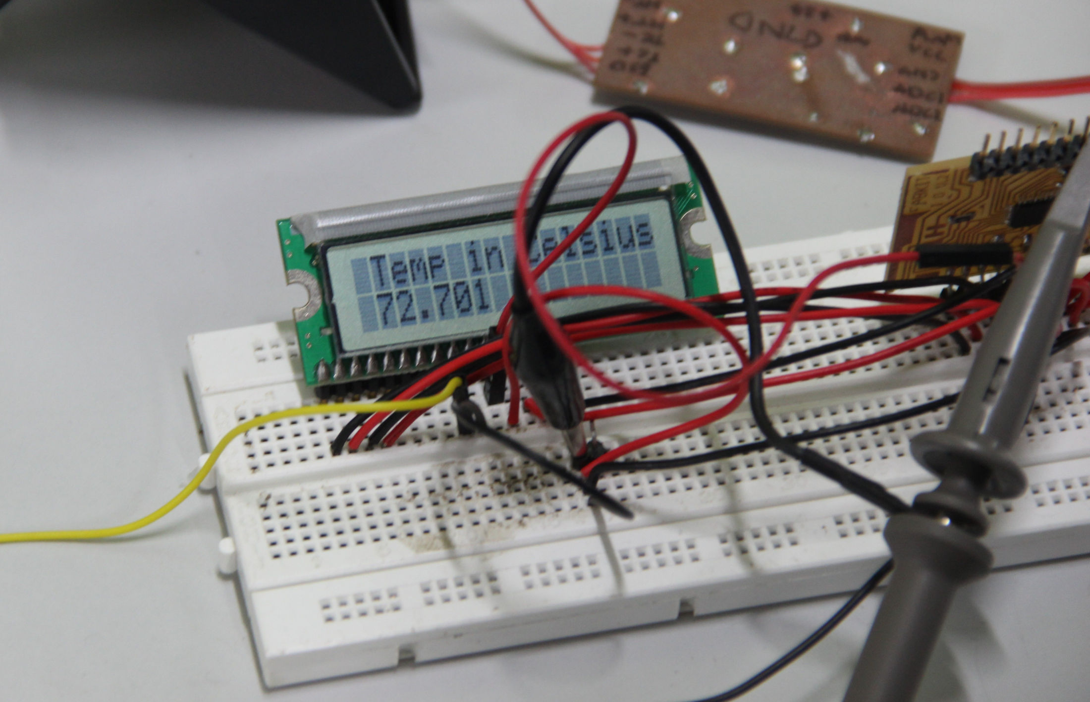
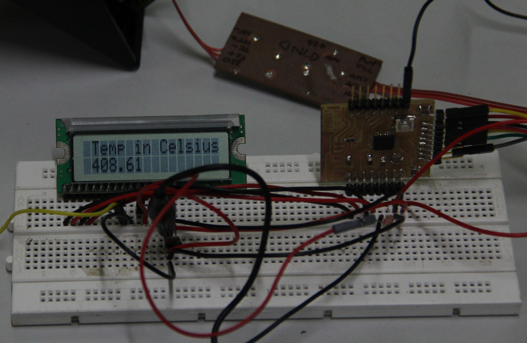
Lets give our project a display and a 'brain'. Yadu had the LCD interfaced with the FabDuino on a breadboard. We connected the amplifier section to the
micr-controller and tried to read the temperature. We got the ADC values displaying, that was easier done than said. But converting the ADC values
to the temperature was not easy. We had to calibrate, for that we needed some source of known temperature or a thermometer. We had none. So I
came up with this crazy setup to get at-least one calibration point, the boiling point of water.
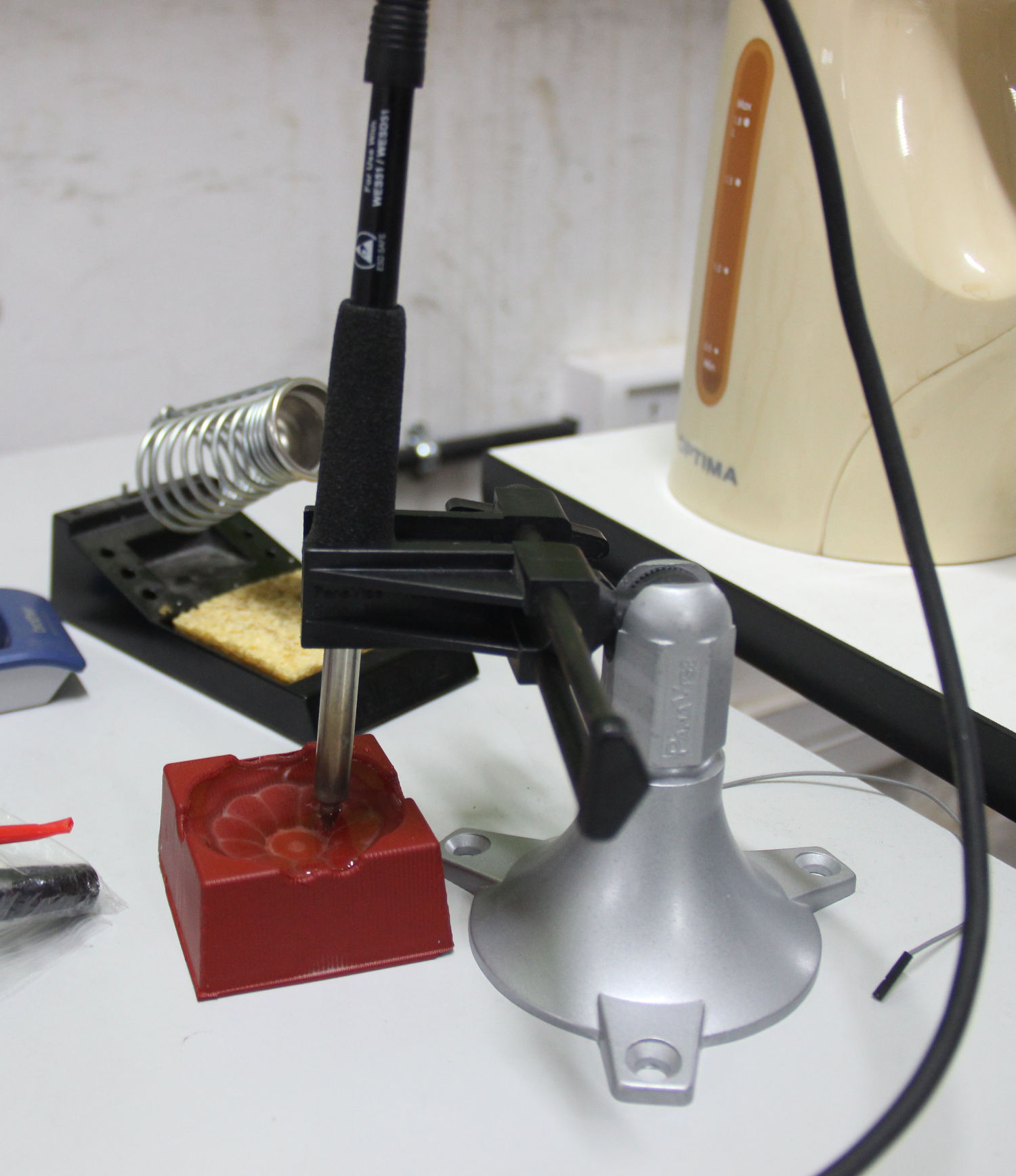
Okay, nice, but how do we use this for calibration ?
Well, we have the tip at a constant and 'known' temperature, let us assume that this is 100℃. Now we get the corresponding ADC reading
through the display, so we know that this ADC readout corresponds to 100℃, to be precise (100-room temperature), because as we discussed
before, the thermocouple measures relative temperature. There should be some way to get the room temperature, a thermometer, but what if you
don't have one?. I used my smartphones's temperature sensor after keeping the phone in sleep for some time to let it cool down to almost the
room temperature.
So, once we have the ADC reading and the room temperature, we can calculate the conversion factor for converting the ADC value to the temperature.
conversion.factor = (100-room.temperature) / ADC.value .
then
tip.temperature = ADC.value * conversion.factor + offset
where offset is the room temperature
I accept, this is a very bad calibration and assumes linear relationship between temperature difference across the thermocouple junction and
the potential difference it produces. But we didn't have any choice. We have to add the NTC and start using it ASAP, but I fear even this may
need a calibration.
Anyway this method will give an approximate tip temperature reading.
          #include

            // initialize the library with the numbers of the interface pins

            LiquidCrystal lcd(7, 6, 5, 4, 3, 2);
            int rawin = 0;
            float  temp =0.0;

            void setup() {
              // set up the LCD's number of columns and rows:

              lcd.begin(16,2);
            }

            void loop() {
              // set the cursor to (0,0):

              lcd.setCursor(1, 0);
              // print from 0 to 9:
              lcd.print("Temp in Celsius");

/*
              char a[32]= "Hello dude, this is Fab Academy";
              for (int i=0; i<32; i++) {
                lcd.setCursor(1,1);
                for (int j=i; j<32; j++) {
                  lcd.print(a[j]);
                }
                delay(500);
              }
*/
              rawin = analogRead(A0);
              temp = rawin * 0.22 + 20.0;
              delay(1);
              lcd.setCursor(1,1);
              lcd.print(temp);
              delay(100);
            }
We used the 16X2 character LCD (LCM-S01602DTR/M). For the LCD interface the connections are..
            * LCD RS pin to digital pin 7
            * LCD Enable pin to digital pin 6
            * LCD D4 pin to digital pin 5
            * LCD D5 pin to digital pin 4
            * LCD D6 pin to digital pin 3
            * LCD D7 pin to digital pin 2
            * LCD R/W pin to ground
            * LCD pins 1 & 2 to +5V and ground
            * LCD VO pin (pin 3) to ground
Also use the ADC0/Pin A0 for the input.
Stage 4: Get control
We are going to use the present tip temperature to control the tip temperature (what? well, thats how it is.) by controlling the power flow. This is done by switching the MOSFET on and off to control the duty cycle and thus the average energy flow (power). The duty cycle control is achieved using PWM (Pulse Width Modulation).
At first, we will be using a simple control, we set a temperature (at first in the program itself, not through the interface), then we switch on the heater if the set temperature (S.T) is greater than present temperature (P.T). And we switch of the heater if P.T > S.T. This method is not very safe as the tip temperature tends to oscillate around or below the S.T. This is because of the delay between the heater control signal and the actual temperature change. We control the heater by switching on and off, the MOSFET, depending on the P.T. When we switch on the heater element gets the full power and heats up very fast, depending on the placement of the actual temperature sensor we can only read this new temperature after a delay, this causes the temperature to overshoot slightly. This in-turn may produce an oscillating behavior. One fix would be to reduce the power to the heater at any given instant. Thus reducing the overshoot. The power-flow can be controlled by adjusting the PWM duty cycle.
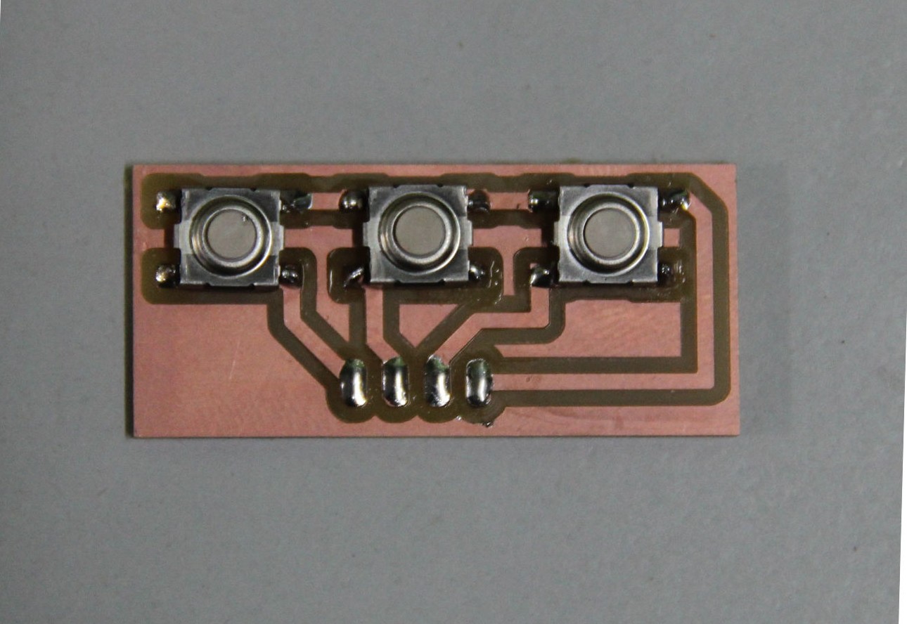
During this time we actually made a three button control board to use in future, to set the temperature and control other functions. We plan to use the
top and bottom buttons for temperature up/down and the middle button for menu election. On pressing any of the button corresponding interrupt
codes will be executed to make changes accordingly.
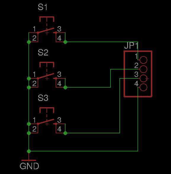
Eagle files
Schematic. Board.