Machine Design Gestalt Board Making
Before you begin, this page is not about the machine design. Since the last module and this one is essentially the part of same goal, I have documented everything in the Mechanical Design module.
I'm using this page to document my experience of trying to make my own version of gestalt stepper controller and milling double sided board. I'll also be using this page for documenting my experience with other controllers, especially networked controllers.
Gestalt Node
For the machine week, we are recommended to use modular design, reconfigurable X,Y and Z stages. So it's better to use modular electronics too. Our instructor Francisco asked me to take a look at the Gestalt Stepper Driver/Gestalt Node. He asked me to go through mtm.cba.mit.edu/machines/stages page and the github page. Later I found a few other useful resources and articles
- The Gestalt Framework
- An Hackaday article which links to this wonderful page.
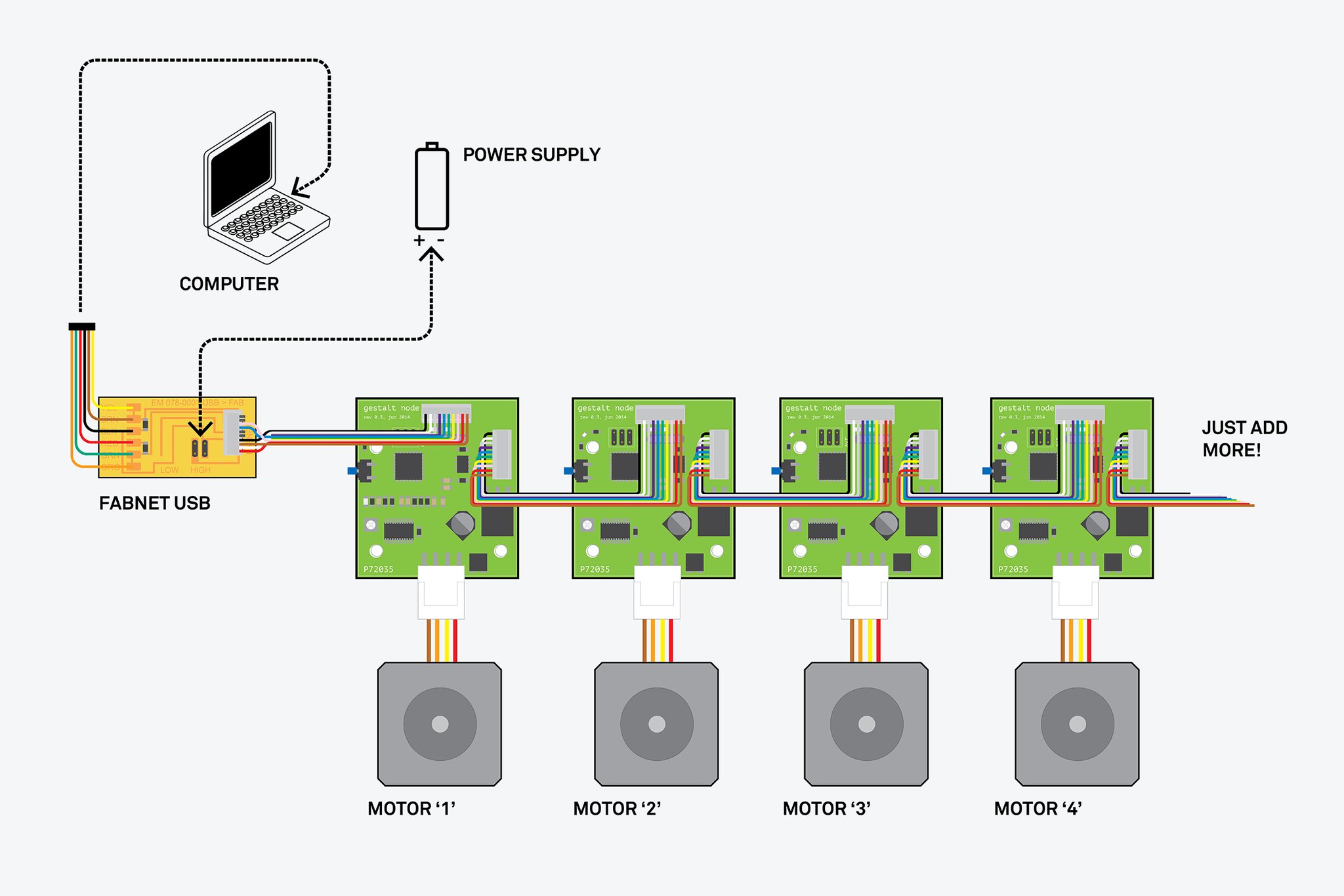
Modified Gestalt Node
These boards are required to make a fully modulular stages. Or it can be something similar, a networked stepper controller like our instructor Franc used for his final project FAB 9000. Anyway I accepted his challenge to make the Gestalt node in-house, because buying them will cost about $500/- as per our instructor. But the BOM will cost much less than that, but there are a few problems, some of the components are not part of the FabLab inventory or some components like the Stepper driver A4982 are not so common in India, but we get (and got) A4988 as breakout boards and they are very cheap. Fortunately I have several of these breakout boards with me.
I also thought about replacing the RS-484 with some easily available and familiar serial protocol, but decided not to, as RS-485 is using a differential pair and capable of long ranges (upto 1200m) and high speed (a few Mbits/s) communication, it also supports several devices in a single daisy chain.
So I decided to redesign the Gestalt node mainly to use A4988 breakout. Other differences include, the modifications on the pads and spacings so that it can be milled in MDX-20 mill.
- The A4982 and several components associated will be replaced by A4988 breakout connector.
- Some of the passive component's package(eagle package) has been changed from smaller 0805 to 1206.
- The pads of the connectors have been elongated so that they won't be too thin after milling, else they will come out while milling, placing the component, cleaning or while soldering.
- Thicker traces for Motor Power Bus.
- A4988 is capable of 1/16 micro-stepping, so I used an extra Digital PIN from the Micro-Controller.
Here is the original Schematic of the Gestalt Node V0.3
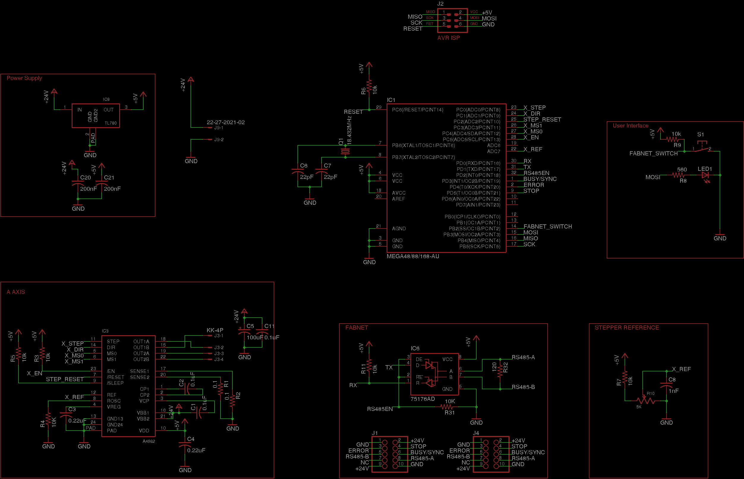
Here is the modified version.

The Boards
Original
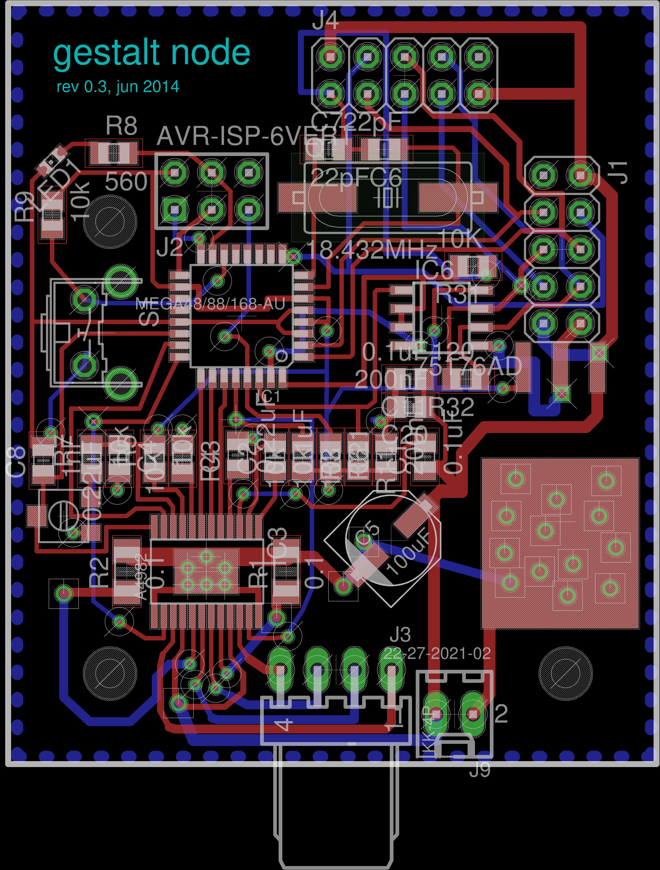
Modified
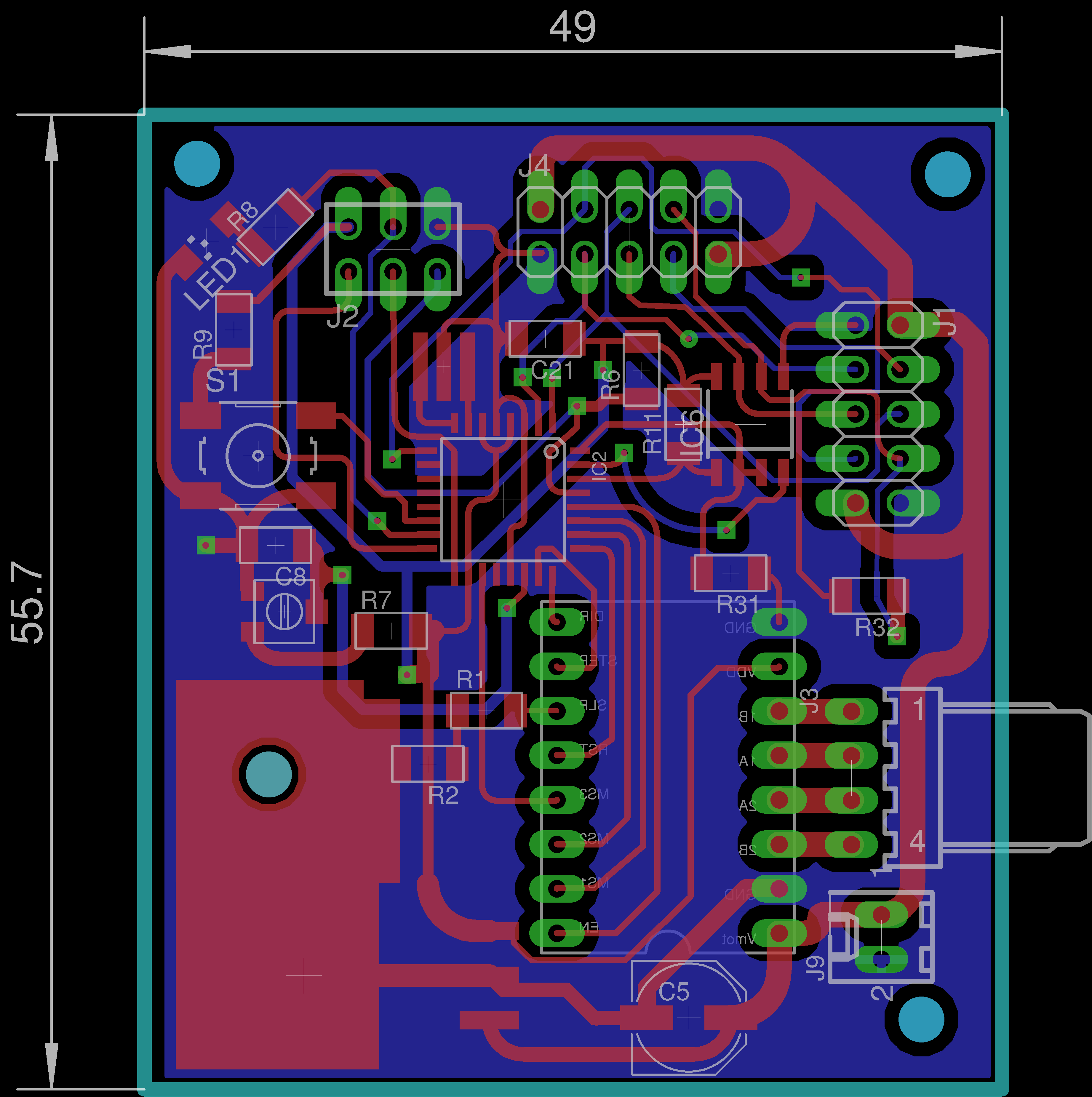
Download Eagle files.
Board. Schematic. Library.
Milling the Double Sided Board
This was the first time I'm doing a double sided board, and nobody here at the lab had the experience of making the double sided board. My initial designs were supposed to be milled with 1/100", in some areas. But that bit is too fragile, event the slightest misalignment (in the leveling), or the flexible nature of the Acrylic workpiece holder was sufficient to break the bit. I had two failed attempt with 1/100".
- First time I could mill one side of the board completely and the bit broke when I started milling the second side, I guess it happened because the rough edges on the other surface might have disturbed the leveling. Another possible reason could be that I milled the entire board out of 1/100" bit, the bit clearly is not made for such heavy duty.
- Second time everything was going perfectly and I used the bit to mill only some small sections where the spacing between the traces/pads are too narrow for the 1/64". So I milled the board using 1/64" first and then moved on to 1/100" for some specific areas. But it failed this time too, during the transition from the cutting zone to an area which was already milled by the 1/64". I cannot find a proper reason for this, though a foolish guess could be that the bit broke when the horizontal load on the bit disappeared suddenly and, caused the bit to release all the 'spring energy' at once which broke it.
- Anyway, I didn't want to experiment more with this expensive fragile 1/100" bit, my final project is anyway an EDM based PCB mill, which in theory could do better than what this machine can do.
Here are the few failed attempts and few test pieces.
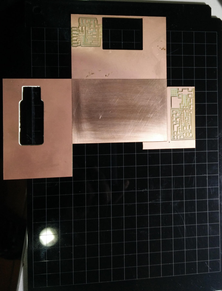
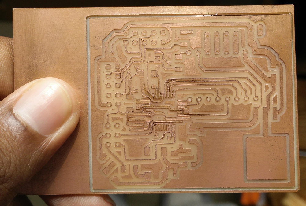
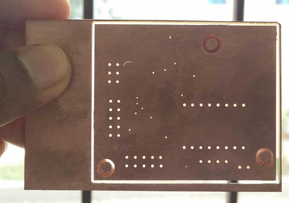
I have refined my design a lot from what is seen above and tuned the board so that it can be milled using 1/64" board, bit at the cost of a few thinner traces (not a big deal) and few extra vias to be milled and soldered. The downloadable eagle files are of the final design.