Mechanical Design
This time, we are supposed to design a machine. I said we, because this is a group assignment. Franc made our big batch of some 14 students at the
FabLab Trivandrum into two groups of 7.
LINK TO THE GROUP PAGE
The group one consist of the following members.
Stage 1. Ideation
Our team members came up with the following ideas, inspired by what's seen in the links.
-
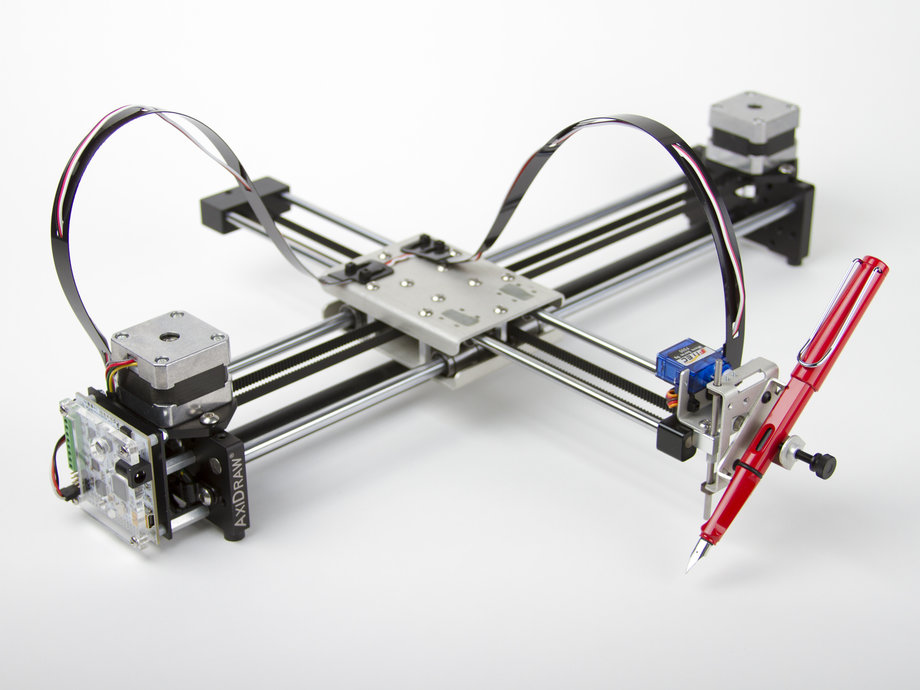
CNC Plotter
-
Foam Cutter
-
Mini CNC Lathe
Source
An example from Alibaba -
Drawing Rover
After the internal discussion, with majority voting for 'CNC Lathe', we decided to pool the resources for the same.
Pooling
We decided to gather all possible resources we could use for this project. From my own experience and a bit of reading, I knew that there are a few things that is a must for a lathe.
- A Headstock with a Chuck to hold the workpiece and a motor to power the spindle.
- A tool-holder/tool-post that can be moved precisely along X and Y. (one along the axis of spindle and other perpendicular to it)
I found the following designs that could be used as it is or could be modified to suit our needs.
Chuck
This is a nice 3D-printable chuck design by
Bob
and made by
Yuri9999 from
Thingiverse
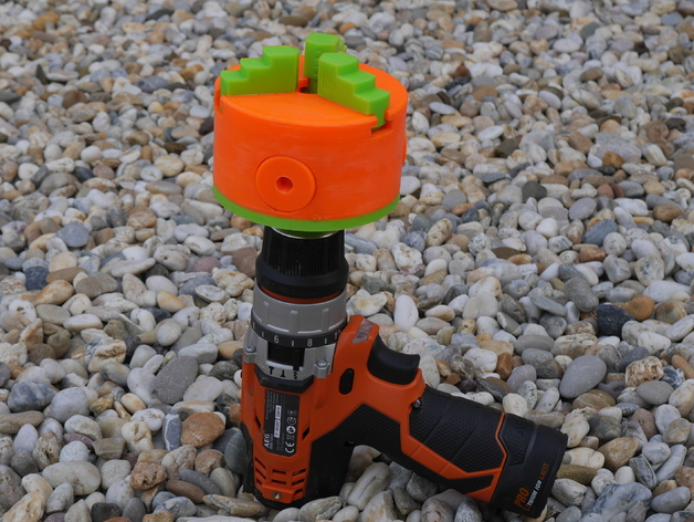
This chuck will hold the workpiece and will be attached to a Drill or some other motor or Dremel tool, though I am doubtful if Dremel has the sufficient Torque for the
purpose, it definitely has the speed.
X-Y Stages.
The tool need to move in the horizontal plane (X and Y), but unlike a 3D-printer XY-stage this need not be fast. In fact it has to be slow and precise movement. So a lead-screw is the
best solution. We plan to use normal threaded rod and bolts for the actuation, as this sis a prototype and proof of concept work. A screw based motion has other advantages
like it can withstand lot of axial load.
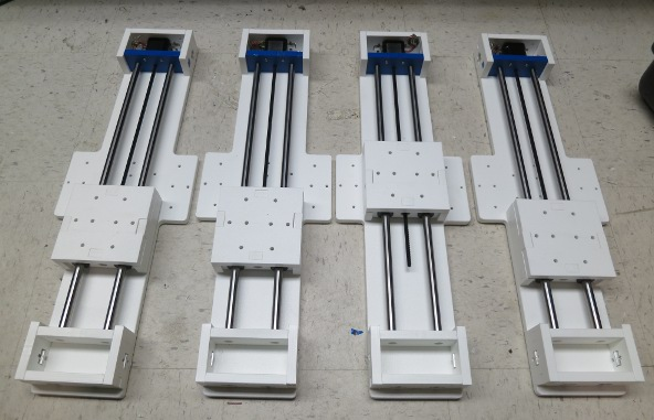
We decided to use a simple stage, two guide rods and a threaded rod at the center attached to a stepper. Something like the first picture in this page, something simple
as the modular stages
Overall design.
The overall final design could be based on the following sources.
https://github.com/Intrinsically-Sublime/Printable-Lathe-V2
He included a 3D-printed chuck too, and powered by a drill just like how we are planing to use.
Another design that we could use is this one,
The OpenSCAD file for which is available
here.
Stage 2. Gathering Parts
Our instructor set a rule of not buying any mechanical components for the machine, instead salvage or make it yourself. A good suggestion, but I personally do not want to strictly adhere to this. As every component we are going to use is bought from somewhere at sometime in some form. So I (and very likely most of us in the lab) will adhere to the rule that "we will be making or salvaging whatever we could, we will do the best we can". This is because not everything could be made or salvaged, for example fasteners, threaded rod, timing belts etc cannot be made, even if we could that won't even match the cheapest options we could find from the market. Then there is time and other resources involved.
Scrap Hunt
Anyway a few of us Me,
Yadu,
Vishnu,
Nadeem and
Safwan went in search of old printers from E-waste collectors. We were hopping to get Motors including stepper motors, threaded rods, smooth rods, timing belts, other
useful mechanical components like gears, springs, screws. We could also get many useful electronics components too, like power-bricks (power bricks of the printers), positions
sensors, switches, connectors etc.
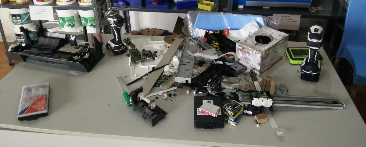
We got a total of 5 printers at an expense of about INR 700 or about USD 10. Since we were at it we also got a few other stuff like two Weller pencils for about INR 30 (about 50 cents),
even if the elements are damaged the thick flexible heat resistant cables in those pencils are worth more than we spent on them.
In summary, this is what we got.
- 9 X DC Motors.
- 1 X Stepper motor.
- 3 X 8mm, 40cm smooth rods.
- 3 X 8mm, 30cm smooth rods with gear like pattern at 1/3rd the length.
- 5 X 6mm smooth rods of various lengths.
- 5 X long timing belts and few shorter ones.
- 2 X Possibly working 230V AC to 19V DC power bricks.
- Many optical positions sensors and endstops.
- Many screws and springs and gears of various types and sizes.
Other parts.
We got the smooth rods for the guide rails. But we couldn't get any threaded rods, and we need it for the machines. There are again multiple options, could use standard threaded rods that are used for fastening, we could use long bolts, or we could use the special high quality threaded rods made for actuation, like the ones used in Ultimaker's Z-axis. There was one vendor who refused to give anything short of 3m. We didn't require long threaded rods as this is an experimental build, need only smaller axes. We could use the long bolts instead, and we decided to do so.
The construction will be using 6mm acrylic and may be the thick, 12mm or 18mm plywood as a base. We will be making a press-fit assembly in acrylic but will also use cyano-acrylic glue
(super-glue) for extra strength.
For the guide rods we planned to use 2 of the 8mm rods and 2 of the 6mm rods.
The stepper motor to the threaded rod coupler will be printed. The design is from
thingiverse.
Electronics
For the electronics, The stepper motor driver chip is
Allegro A4988 in a
Breakout board.
The stepper used will be the NEMA17 ones available in the Fablab inventory.
The main controller board can be my
RAMPS_1.4. Or it could be the
Gestalt Node V0.3 mod I'm making (
Documentation). This board is mod so that ot uses the A4988 breakout instead of A4982.
Though I really don't want to use this board for the following reasons.
- We don not need the flexibility/modularity provided by the networked controller nodes.
- It's a huge waste of resources, one Atmega328p, a crystal/resonator, the RS485 transceiver chip and whole lot of other passive electronic components for just controlling a stepper motor.
- The Atmega328p might be capable of controlling the two steppers and other things I wanted to solely.
- The framework is not mature enough. Or in other words it under heavy development.
- At present RAMPS 1.4 gives me more flexibility and options for expansion.
- ....
Stage 3. Construction
The difficult part would be the construction of the X-Y stages, the mechanical, linear movements for the X and Y axes. For some reason first we printed the parts that are required only
at the last, perhaps we just wanted to start and these prints were made using ready to print files from thingiverse.
First we printed the parts for the chuck.
Chuck
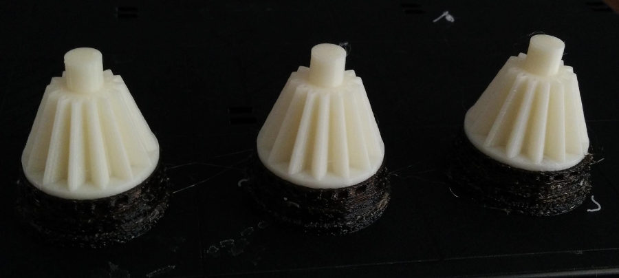
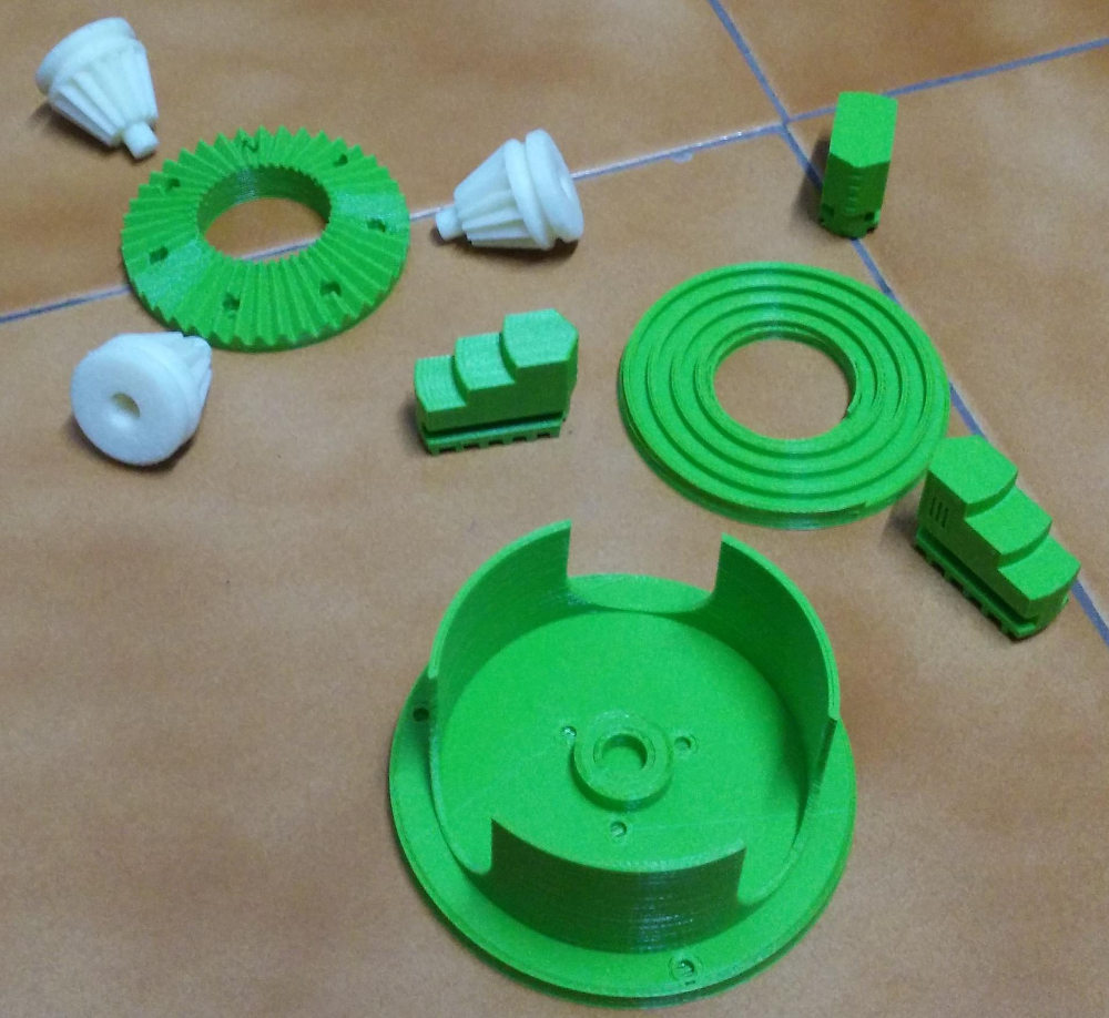
More details
here.
X and Y axes
Now comes the actual difficult part of the project. We need to design the X and Y stages using the materials available at the lab and the salvaged parts.
We decided to make something simple using the smooth rods we have and the two long bolts. The basic design comes from my
Computer-Controlled Cutting module, where I did a press-fit box in OpenSCAD. I modified the file to get the moving carriage and the overall axes. This is the modified
OpenSCAD file for the X or Y carriage, The holes are meant for m8 threaded rod. The holes for the guide rods are such that either m6 or m8 smooth rods, the two set of walls
has two different holes.
module copy_mirror_adj(vec=[1,1,0])
      {
        children();
        mirror([1,0,0])mirror(vec) children();
      }
module copy_mirror_opp(vec=[0,1,0])
      {
        children();
        mirror(vec) children();
      }
module copy_tran(vec=[0,0,0])
      {
        children();
        translate(vec) children();
      }

      $fn = 64; //smoother render, this number gives how many frangments are used for a circle

      l = 60;
      b = 60;
      h = 30;

      base_raise = 0;

      beam_width= .4;
      thick = 6;

      g_rod_1_dia = 5.95;
      g_rod_2_dia = 7.95;
      t_rod_dia = 8 ;

      number_of_slots_base_len = 3;
      number_of_slots_base_wid = 3;
      number_of_slots_wall = 2;

      wall_length = l;
      wall_width = b;
      wall_height = h+2*thick;

      num_slots_base_l = number_of_slots_base_len * 2;
      num_slots_base_b = number_of_slots_base_wid * 2;
      num_slots_wall_side = number_of_slots_wall * 2;
      base_slot_width_l = l / ( num_slots_base_l + 1);
      base_slot_width_b = b / ( num_slots_base_b + 1);
      fit_base_slot_width_l = base_slot_width_l + beam_width;
      fit_base_slot_width_b = base_slot_width_b + beam_width;
      wall_slot_width = wall_height / ( num_slots_wall_side + 1);
      fit_wall_slot_width = wall_slot_width + beam_width;
      slot_depth = thick;

//base and top
      copy_tran([l + 2*thick +1,b + 2*thick +1, 0])
      union(){
          translate([-l/2,-b/2,0])
          union(){
            for ( i = [ 1: 2: num_slots_base_l ] ) //top and bottom slots
            {
                translate ( [ 0, b, 0 ] )
                translate ( [ (i+.5) * base_slot_width_l , slot_depth/2, 0 ] )
                square ( size = [ fit_base_slot_width_l, slot_depth ], center = true );

                translate ( [ 0, -slot_depth, 0 ] )
                translate ( [ (i+.5) * base_slot_width_l , slot_depth/2, 0 ] )
                square ( size = [ fit_base_slot_width_l, slot_depth ], center = true );
            }

            for ( i = [ 1: 2: num_slots_base_b ] ) //left and right slots
            {
                translate ( [ l, 0, 0 ] )
                translate ( [ slot_depth/2, (i+.5) * base_slot_width_b, 0 ] )
                square( size = [ slot_depth, fit_base_slot_width_b ], center = true );

                translate ( [ -slot_depth, 0, 0 ] )
                translate ( [ slot_depth/2, (i+.5) * base_slot_width_b, 0 ] )
                square (size = [ slot_depth, fit_base_slot_width_b ], center = true );
            }
            square ( size = [l, b], center = false );
            }
    }

//wallls
//top and bottom walls
    copy_mirror_opp(vec=[0,1,0])
    translate([-l/2,-b/2,0])
    union()
    {
        difference()
        {
            translate ( [ 0, b+1+2*thick, 0 ] )
            square ( size = [wall_length, wall_height], center = false );

            for ( i = [ 1: 2: num_slots_base_l ] )
                {
                    translate ( [ 0, b + 1 + 2*thick + base_raise, 0 ] )
                    translate ( [ (i+.5) * base_slot_width_l, slot_depth/2, 0 ] )
                    square ( size = [ base_slot_width_l, slot_depth ], center = true );
                }
            for ( i = [ 1: 2: num_slots_base_l ] )
                {
                    translate ( [ 0, b + 1 + thick + base_raise + wall_height, 0 ] )
                    translate ( [ (i+.5) * base_slot_width_l, slot_depth/2, 0 ] )
                    square ( size = [ base_slot_width_l, slot_depth ], center = true );
                }

            translate([2*thick, b + 1 + 3*thick + base_raise + g_rod_1_dia, 0 ])
            circle(d=g_rod_1_dia);

            translate([l-2*thick, b + 1 + 3*thick + base_raise + g_rod_1_dia, 0 ])
            circle(d=g_rod_1_dia);

            translate([l/2, b + 2 + 3*thick + base_raise + t_rod_dia, 0 ])
            circle(d=t_rod_dia);
        }
        for ( i = [ 0: 2: num_slots_wall_side ] )
            translate ( [ l, b+1+2*thick, 0 ] )
            translate ( [ slot_depth/2, (i+.5)*wall_slot_width, 0 ] )
            square( size = [ slot_depth, wall_slot_width], center = true );

        for ( i = [ 0: 2: num_slots_wall_side ] )
            translate ( [ -slot_depth, b+1+2*thick, 0 ] )
            translate ( [ slot_depth/2, (i+.5)*wall_slot_width, 0 ] )
            square (size = [ slot_depth, wall_slot_width ], center = true );
    }

//left and right walls
    copy_mirror_opp(vec=[1,0,0])
    mirror([1, 1, 0])
    translate([-b/2,-l/2,0])
    union()
    {
        difference()
        {
            translate ( [ 0, l+1+2*thick, 0 ] )
            square ( size = [wall_width, wall_height], center = false );

            for ( i = [ 1: 2: num_slots_base_b ] )
            {
                translate ( [ 0, l + 1 + 2*thick + base_raise, 0 ] )
                translate ( [ (i+.5) * base_slot_width_b, slot_depth/2, 0 ] )
                square ( size = [ base_slot_width_b, slot_depth ], center = true );
            }
            for ( i = [ 1: 2: num_slots_base_b ] )
            {
                translate ( [ 0, l + 1 + thick + base_raise + wall_height, 0 ] )
                translate ( [ (i+.5) * base_slot_width_b, slot_depth/2, 0 ] )
                square ( size = [ base_slot_width_b, slot_depth ], center = true );
            }

            translate([2*thick, l + 1 + 3*thick + base_raise + g_rod_2_dia, 0 ])
            circle(d=g_rod_2_dia);

            translate([b-2*thick, l + 1 + 3*thick + base_raise + g_rod_2_dia, 0 ])
            circle(d=g_rod_2_dia);

            translate([b/2, l + 2 + 3*thick + base_raise + t_rod_dia, 0 ])
            circle(d=t_rod_dia);
        }

        for ( i = [ 1: 2: num_slots_wall_side ] )
            translate ( [ wall_width, l+1+2*thick, 0 ] )
            translate ( [ slot_depth/2, (i+.5)*wall_slot_width, 0 ] )
            square( size = [ slot_depth, fit_wall_slot_width], center = true );

        for ( i = [ 1: 2: num_slots_wall_side ] )
            translate ( [ -slot_depth, l+1+2*thick, 0 ] )
            translate ( [ slot_depth/2, (i+.5)*wall_slot_width, 0 ] )
            square (size = [ slot_depth, fit_wall_slot_width ], center = true );
SVG. DWG. DXF.
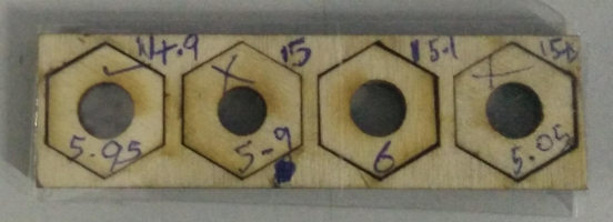
The X-Y carriage design is ready, now we need to make an assembly for this box to slide. The base design for this also came from the above OpenSCAD design, this file is also edited in Rhino to have the mounting holes. The sizes of the stages are determined by the length of the smooth rods we have.
During the construction we actually made a few mistakes and wasted a few pieces of acrylic, I should have done a test cut on cardboard before!.
So, it's time for the redemption, to compensate for the wasted acrylic I decided to do the test cuts in a cardboard sheet cut from package.


'Machines that make the machines'
We were supposed to be making a lathe, but we had to do a makeshift lathe to,
- Cut a few of the smooth rods to length.
- Cut the head of the long bolts used for the actuation.
- Cut a few bolts to length, used for mounting.
The X-Y stages at work
This is our first attempt to control the stepper via Gcode and first real test on my stage design. For more details head over to our
team page and
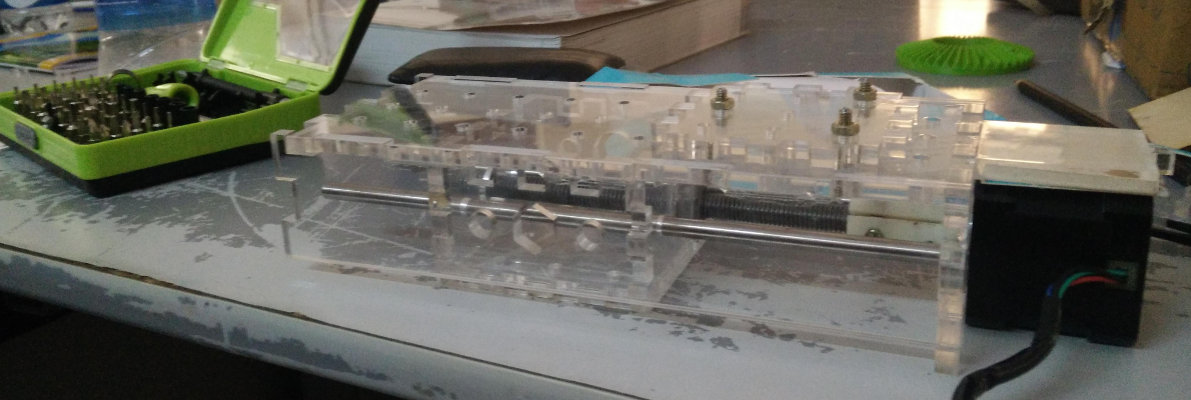
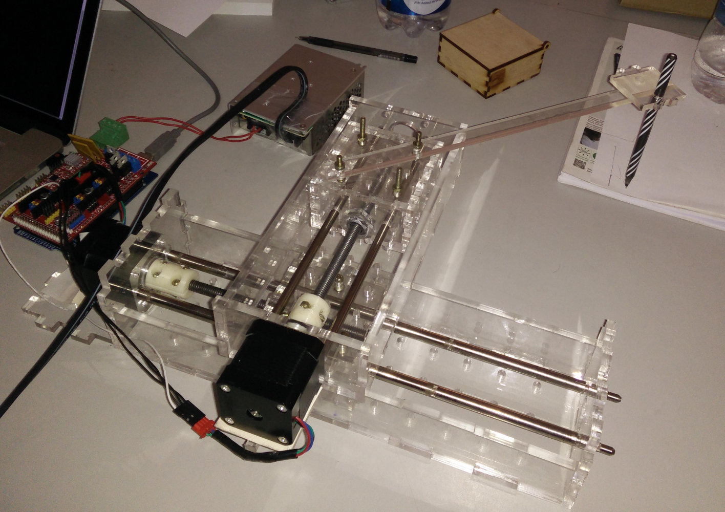
Yogi's page who is in charge of all the coding and stuff. Having made the X-Y stages and mounted the steppers, then merged the two stages to a single unit and used the
RAMPS 1.4 controller board. We decided to use the PC for the hard stuff, generating the Gcode and stuff. The serial communication is used to transfer the Gcodes, individually
to the controller board and the Atmega2560 (Arduino Mega) will interpret the Gcode and will send the required signals to the motor controller, A4988. The micro controller
need to send three set of data,
- Enable (high/low):- to enable/disable the stepper, enabling means the stepper will always have power, whether it moves or not. When enabled the coils are energized and when not rotating, it holds it's position well, withstands a lot of load(external torque) before it spins. Obviously this has to be enabled if one wishes to use the stepper.
- Dir (high/low):- sets the direction of rotation.
- Steps (Pulses):- each pulse moves the stepper by one step.
The motor and the board is powered by a 230V to 12V 3A AC-DC SMPS.
You can see a video of getting both the to move using the stepper via the serial interface between the computer and the micro-controller.
For more details on programming and controls head over to our
team page and Yogi's page.!!!TWIST!!!
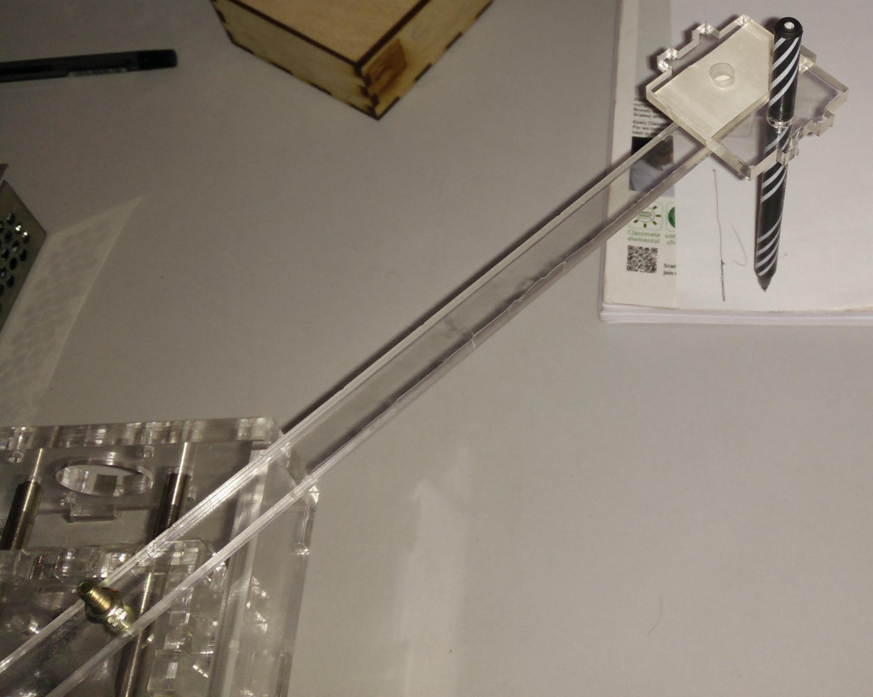
Perhaps you noticed it already, we started with the plan to make a lathe and ended up making a plotter. We may still continue with the lathe, the difficult part was the constructions
and controlling of the stages, which has been achieved.
Though we tried for a square, we got something entirely different, but wait, who writes anything right the first time, this is our 'baby' and we are teaching it.
We have more results at our team page.
Problems and failures.
Some of the problems I faced with the mechanical parts.
- For the X-axis I used two nuts and a spring to keep them 'loaded'/under pressure. This worked great, there has been absolutely no problem with this stage except for the expected ones due to the bolt we used. The bolt we used is not meant for actuation purpose, it's not consistent or perfectly straight, this was causing some wobbliness.
- During the constructions of the second/Y-stage, there was an issue of misalignment, the nuts glued onto the Y-carriage was offset and was causing massive load on the motor and it was getting stuck/stalled. I fixed this by removing the nut and fixing it at the correct position.
- The bolt used for Y has a bent/dent or some kind of damage at the middle and the motor will get stuck stalled at the middle, so far we are unable to solve this. The best solution would be to get a new bolt.
This has been a bigger problem for the Y-stage as the holes for the guide rods are not symmetric(symmetry over the horizontal plane).