Embedded Programming
Goals for this module includes
- Go through the microcontroller/microprocessor data sheets and document what I have learned.
- Program a 'Hello World' board I made before; in my case, the Fabduino variant I made before.
- Try different options to program the board; I'm planning to try Arduino IDE, pure C (avr-c) and assembly.
- For extra credit, try a different architecture.
I have already programmed my board using Arduino IDE. I spent some time setting up the Arduino environment, added the new 20MHz variant to the list of the boards (boards.txt), added
new bootloader and new makefile. I also setup the Udev rules and few other tweaks, you can read about those in my
Electronics Design page.
I didn't make the bootloader hex file or the makefile, I just sources it from various locations in Internet, so this is the time to learn about those too, means I will
be trying to compile my own Arduino bootloader and Makefile.
So my goals for this module is.
- Go through the microcontroller/microprocessor data sheets and document what I have learned.
- Try Arduino IDE, AVR-C and assembly to program the Faduino I made.
- Create a makefile for compiling the avr-c code and programming.
- Since I have access to AVR and PIC boards as well as ARM (Raspberry PI), I may try some of them.
So I have downloaded the datasheet for the 8bit AVR microcontrollers,
ATmega48A/PA/88A/PA/168A/PA/328/P
. I will be going through this documentation as and when I require.
For those who are interested in the board I'm using; this is a 20MHz variant of the Fabduino I made during
Electronics Design.
So, Lets begin....
Programming With Arduino IDE and AVR C.
The Arduino Code
For Blinking the LED.
void setup() {
  // initialize digital pin 13 as an output.
  pinMode(13, OUTPUT);
}

void loop() {
  digitalWrite(13, HIGH);   // turn the LED on (HIGH is the voltage level)
  delay(1000);              // wait for a second
  digitalWrite(13, LOW);    // turn the LED off by making the voltage LOW
  delay(1000);              // wait for a second
}
The AVR C Code
Essentially the same code as above.
#define F_CPU 20000000UL
#include <avr/io.h>
#include <util/delay.h>

#define BLINK_DELAY_MS 1000

int main (void)
{
  /* set (PB5) of PORTB for output*/
  //DDRB = (1<<PB5);
  DDRB = 0b00100000; //does the same thing as above line
  while(1)
  {
    /* pin 5 high = turn led on */
    PORTB = 0b00100000;
    _delay_ms(BLINK_DELAY_MS);
    /* pin 5 low = turn led off */
    PORTB = 0b00000000;
    _delay_ms(BLINK_DELAY_MS);
  }
}
This code is written with the help of datasheet of the AtMega328p, specifically section 14.2 on
Ports as General Digital I/O and my own experience.
The following shell script was written to automate the compilation and uploading.
rm out*
avr-gcc -Os -DF_CPU=20000000UL -mmcu=atmega328p -c -o out.o blink0.1.c
avr-gcc -mmcu=atmega328p out.o -o out
avr-objcopy -O ihex -R .eeprom out out.hex
avrdude -F -V  -p ATMEGA328P -P usb -c usbtiny -b 115200 -U flash:w:out.hex
Makefile
DEVICE  = atmega328p
F_CPU   = 20000000	# in Hz
FUSE_L  = 0xFF # 0xE2 for internal 8Mhz 0xFF for external and 0X62 for internal 1MHz
FUSE_H  = 0xDF
AVRDUDE = avrdude -c usbtiny -P usb -F -V -b 115200 -p $(DEVICE) # edit this line for your programmer

CFLAGS  = -Wall -Os
OBJECTS = main.c

COMPILE = avr-gcc -DF_CPU=$(F_CPU) $(CFLAGS) -mmcu=$(DEVICE)

help:
	@echo "This Makefile has no default rule. Use one of the following:"
	@echo "make hex ....... to build main.hex"
	@echo "make program ... to flash fuses and firmware"
	@echo "make fuse ...... to flash the fuses"
	@echo "make flash ..... to flash the firmware (use this on metaboard)"
	@echo "make clean ..... to delete objects and hex file"

hex: main.hex

program: flash fuse

# rule for programming fuse bits:
fuse:
	@[ "$(FUSE_H)" != "" -a "$(FUSE_L)" != "" ] || \
		{ echo "*** Edit Makefile and choose values for FUSE_L and FUSE_H!"; exit 1; }
	$(AVRDUDE) -U hfuse:w:$(FUSE_H):m -U lfuse:w:$(FUSE_L):m

# rule for uploading firmware:
flash: main.hex
	$(AVRDUDE) -U flash:w:main.hex:i

# rule for deleting dependent files (those which can be built by Make):
clean:
  rm -f main.hex  main.elf *.o

main.elf:
	$(COMPILE) -o main.elf $(OBJECTS)

main.hex: main.elf
	rm -f main.hex main.eep.hex
	avr-objcopy -j .text -j .data -O ihex main.elf main.hex
	avr-size main.hex

# debugging targets:
disasm:	main.elf
	avr-objdump -d main.elf
It's working, but,
We Have A Problem
The video has two boards, an Arduino UNO clone based on Atmega328p working at 16MHz and my board which is also based on the same chip but supposedly working at 20MHz. Both
the boards are running the same code for blinking the LED, one second on and one second off.
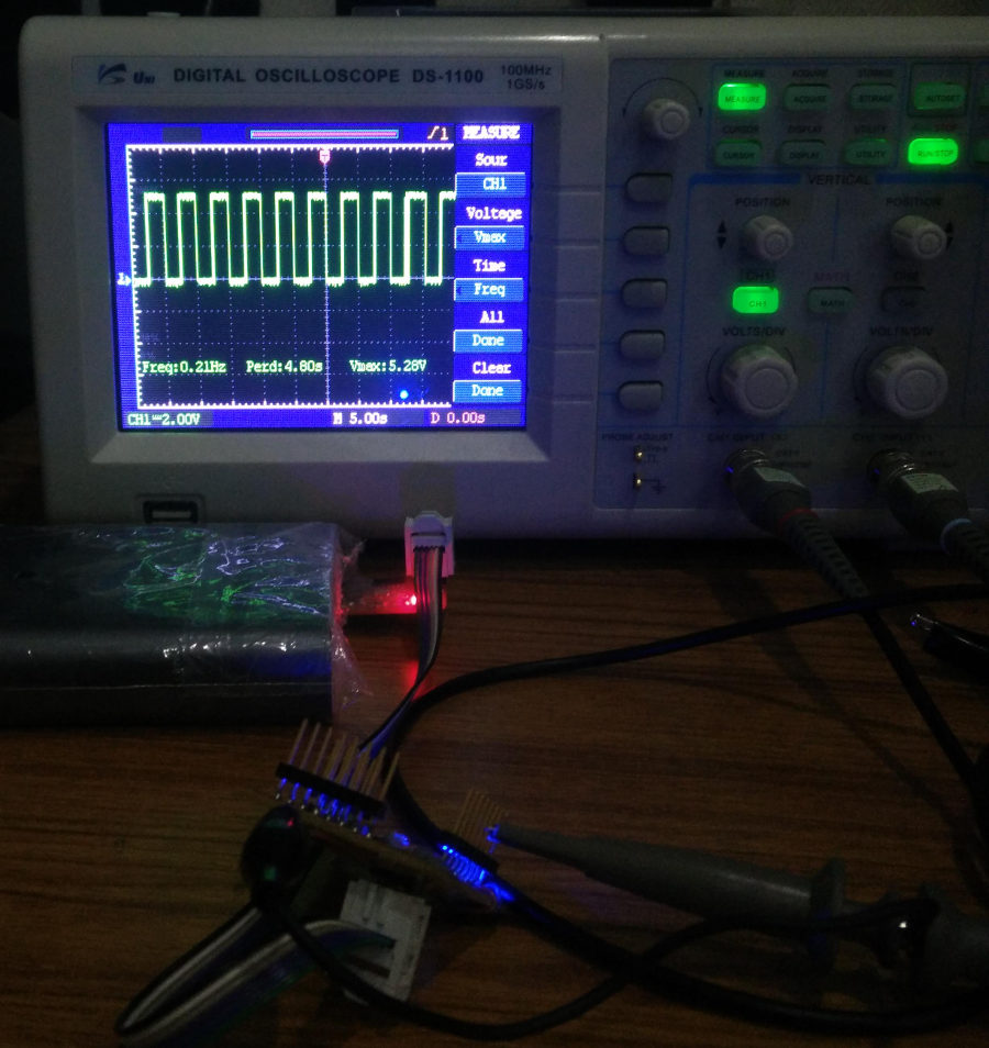
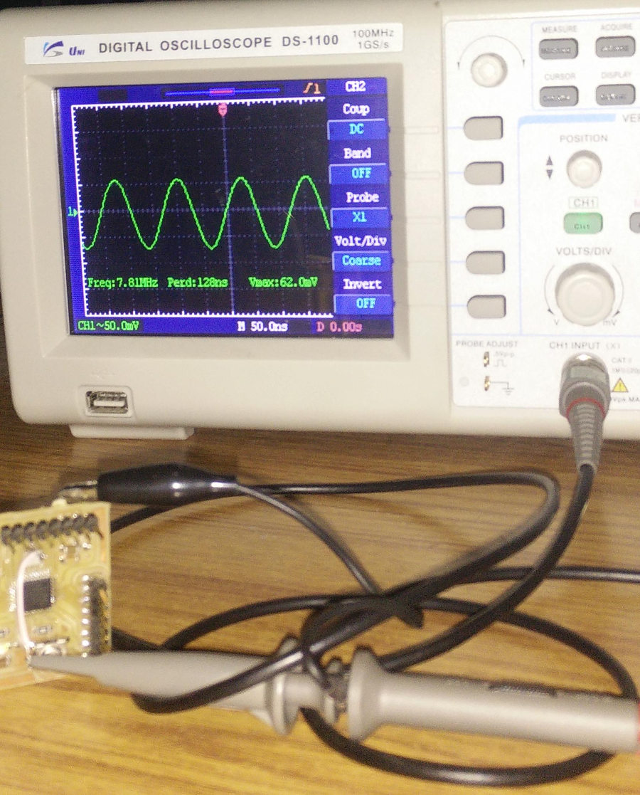
As you can see, my board is clearly not pulsing with one second delay, it's way above one second. Something is wrong, and I guess it's the clock speed. I defined 20MHz
clock in program and during compilation and the chip is not running at a lower clock. So if the chip was indeed working at 20MHz I wouldn't face such an error. So I suspect
three things,
- I used a 8MHz resonator, (that is the only other resonator we have in the inventory)
- The connection/soldering of the resonator/IC pins is not proper.
- The chip was programmed with wrong FUSE bits when I programmed it the first time, I don't exactly rememberer what values I used. So if I had messed up here the chip may not accept external clock.
So Why Is Clock Important?
For normal operations the clock is not necessary, for example you want your board to control some appliances based on some user inputs, such as turn on the lights when the sun goes
down, or a solar tracker using a few motors(not servos or steppers) and light sensors.
But for anything where the timing is important, such as communication, servo/stepper/BLDC motor control etc. or even the simple blinking LED program require precise timing.
The Microcontroller should work at a precise known clock speed, else we will have no control over the 'time'.
From the datasheet, I know that the chip has an internal clock and independent watchdog timers (I will explore this later). The internal clock is limited to 8MHz, you may
be overclock it and get higher clock speed, but that's not good, because the internal clock generator is unreliable above 8Mhz, so time critical functions such as communication
will fail. For any value above 8MHz, upto a limit of 20MHz we can use external clock.
'Time' To Fix The 'Timing'
First thing I did is to see what happens if I compile the program with -DF_CPU=8000000UL instead of-DF_CPU=20000000UL.
As expected the LED starts blinking with one Second delay; so the problem is what is suspected, chip running at lower clock.
First I tried too read the FUSE bits.
        sibu@manjaro emb % avrdude -P usb -b 19200 -c usbtiny -p m328p -v

         avrdude: Version 6.3, compiled on Feb 21 2016 at 13:33:25
         Copyright (c) 2000-2005 Brian Dean, http://www.bdmicro.com/
         Copyright (c) 2007-2014 Joerg Wunsch

         System wide configuration file is "/etc/avrdude.conf"
         User configuration file is "/home/sibu/.avrduderc"
         User configuration file does not exist or is not a regular file, skipping

         Using Port                    : usb
         Using Programmer              : usbtiny
         Overriding Baud Rate          : 19200
         avrdude: usbdev_open(): Found USBtinyISP, bus:device: 001:011
         AVR Part                      : ATmega328P
         Chip Erase delay              : 9000 us
         PAGEL                         : PD7
         BS2                           : PC2
         RESET disposition             : dedicated
         RETRY pulse                   : SCK
         serial program mode           : yes
         parallel program mode         : yes
         Timeout                       : 200
         StabDelay                     : 100
         CmdexeDelay                   : 25
         SyncLoops                     : 32
         ByteDelay                     : 0
         PollIndex                     : 3
         PollValue                     : 0x53
         Memory Detail                 :

                                  Block Poll               Page                       Polled
           Memory Type Mode Delay Size  Indx Paged  Size   Size #Pages MinW  MaxW   ReadBack
           ----------- ---- ----- ----- ---- ------ ------ ---- ------ ----- ----- ---------
           eeprom        65    20     4    0 no       1024    4      0  3600  3600 0xff 0xff
           flash         65     6   128    0 yes     32768  128    256  4500  4500 0xff 0xff
           lfuse          0     0     0    0 no          1    0      0  4500  4500 0x00 0x00
           hfuse          0     0     0    0 no          1    0      0  4500  4500 0x00 0x00
           efuse          0     0     0    0 no          1    0      0  4500  4500 0x00 0x00
           lock           0     0     0    0 no          1    0      0  4500  4500 0x00 0x00
           calibration    0     0     0    0 no          1    0      0     0     0 0x00 0x00
           signature      0     0     0    0 no          3    0      0     0     0 0x00 0x00

         Programmer Type : USBtiny
         Description     : USBtiny simple USB programmer, http://www.ladyada.net/make/usbtinyisp/
         avrdude: programmer operation not supported

         avrdude: Using SCK period of 10 usec
         avrdude: AVR device initialized and ready to accept instructions

         Reading | ################################################## | 100% 0.00s

         avrdude: Device signature = 0x1e950f (probably m328p)
         avrdude: safemode: hfuse reads as DE
         avrdude: safemode: efuse reads as FD

         avrdude: safemode: hfuse reads as DE
         avrdude: safemode: efuse reads as FD
         avrdude: safemode: Fuses OK (E:FD, H:DE, L:FF)

         avrdude done.  Thank you.
Okay,


Anyway, my board is working fine now, no timing issues.
Assembly code for Blinking LED.
For the assembly code, we need to create a delay between toggling the LEDs. There are no pre-built functions like
_delay_ms(); in C or delay(); in Arduino IDE. One method is to waste clock cycles, just like the functions _delay_ms(); in C or delay(); in Arduino does. But we will have to
write our own routine for this. We can waste clock cycles by making the chip loop through a few calculations or something, since we can calculate how many clock cycles are
required by each of those instructions and we know the time period of the clock, we can calculate the length of the loop so that we get a desired delay by executing this
routine.
I found a few sources which would help me do this
- http://stackoverflow.com/questions/24097526/how-to-make-a-delay-in-assembly-for-avr-microcontrollers
- http://bretmulvey.com/avrdelay.html
.equ	DDRB	, 0x04
.equ	PORTB	, 0x05

.org 0
jmp 16
.org 16

wdr

main:
    ldi r16, 0b00100000
    out DDRB,r16            ; Set PB5 to output
    out PORTB,r16           ; Set PB5 high

loop:
    call delay
    sbi PORTB, 5
    call delay
    cbi PORTB, 5
    rjmp loop
delay:
    ldi  r18, 102
    ldi  r19, 118
    ldi  r20, 194
L1: dec  r20
    brne L1
    dec  r19
    brne L1
    dec  r18
    brne L1
    ret
wasting the clock cycles to blink LED is not an ideal solution, in fact this is a waste of time. The chip is actually capable of doing much more and blinking an LED shouldn't consume all the resources. The solution is to use Internal/External Timers and interrupts. There are three timers in Atmeg328P, out of which one, Timer1 is a 16bit timer/counter. The other two, Timer0 and Timer2 are 8bit/timer/counter. There is a separate 128KHz watchdog timer too these timers/counters can be used to trigger corresponding interrupts and the interrupt routine can have the instructions to toggle the LEDs.
Interrupt Based Blink LED Program.
Arduino code.
// Arduino timer CTC interrupt example
#include <avr/io.h>
#include <avr/interrupt.h>
#define LEDPIN 13
void setup()
{
pinMode(LEDPIN, OUTPUT);
// initialize Timer1
cli();          // disable global interrupts
TCCR1A = 0;     // set entire TCCR1A register to 0
TCCR1B = 0;     // same for TCCR1B

// set compare match register to desired timer count:
OCR1A = 19530;

// turn on CTC mode:
TCCR1B |= (1 << WGM12);

// Set CS10 and CS12 bits for 1024 prescaler:
TCCR1B |= (1 << CS10);
TCCR1B |= (1 << CS12);

// enable timer compare interrupt:
TIMSK1 |= (1 << OCIE1A);

// enable global interrupts:
sei();
}

void loop()
{
// main program
}

ISR(TIMER1_COMPA_vect)
{
digitalWrite(LEDPIN, !digitalRead(LEDPIN));
}
The program is from
https://arduinodiy.wordpress.com/2012/02/28/timer-interrupts/
The program counts till a number
x and when the counter reaches x it triggers an interrupt. This mode is called
Clear Timer on Compare Match, or
CTC. The interrupt routine has the code to toggle the LED.


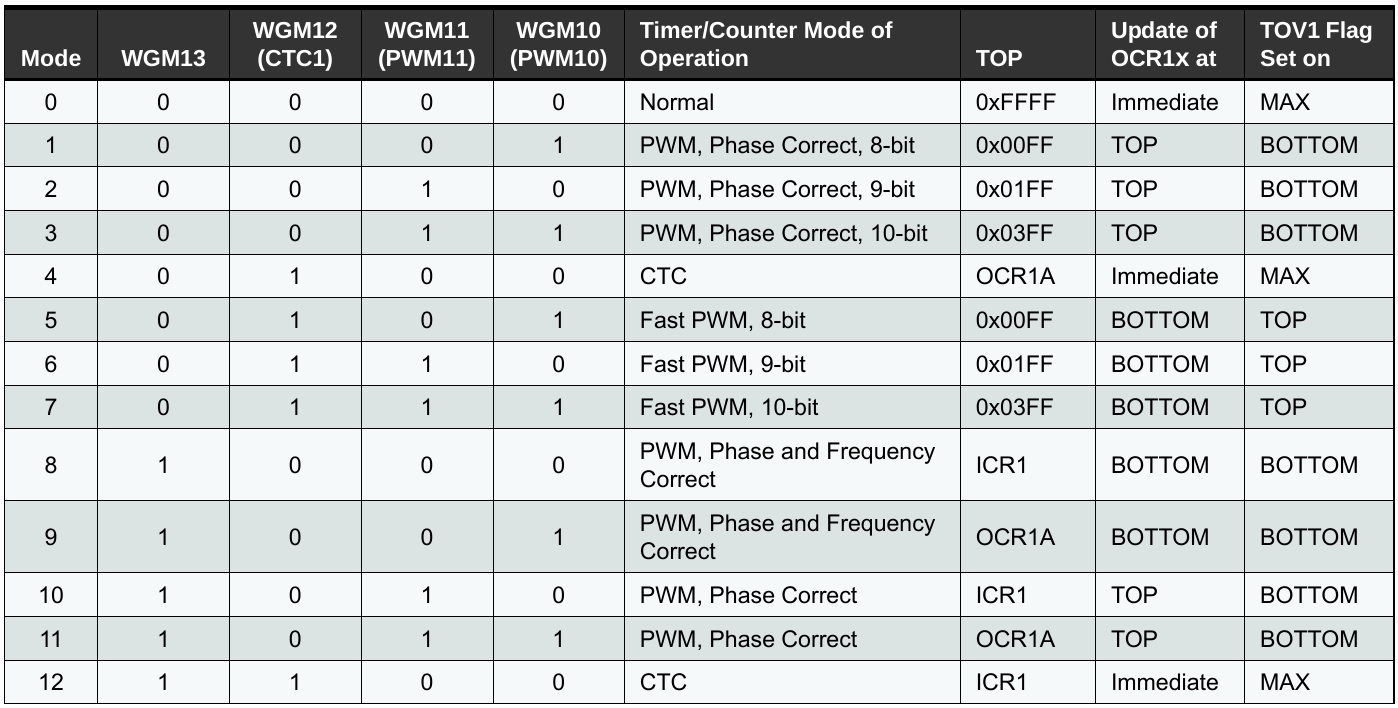
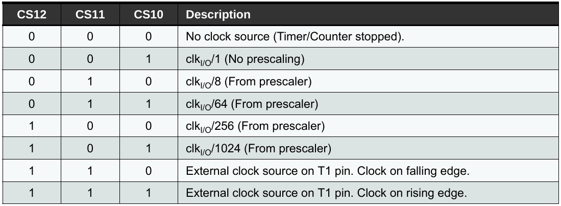
WGM12 bit high to enable CTC mode, CS10 and CS12 bits are set high to enable 1024 prescaler, this means for
every 1024 clock cycles the counter will increase by one.
OCR1A is a 16bit register to store the target count, and when the counter reaches this number it will trigger an interrupt vectored to 0x0016 or
TIMER1_COMPA_vect. We can keep our 'toggle LED' program here.
OCIE1A bit of TIMSK1 register should be set high to enable the Timer1 compare interrupt, interrupt when the timer reaches the values set at OCR1A.
How do we calculate the value of OCR1A???
We know that the Timer1 increases by one for every 1024 system clock. Suppose the system clock is at F Hz, the period or the time resolution is 1/F seconds. So the Timer one takes 1024 * 1/F or 1024/F seconds per increment. So for t seconds of delay, we will have t*F/1024 counts in the Timer1. So this is the value we need to keep at OCR1A for a t second delay.
To be very precise the calculation is actually OCR1A = (t*F/prescale) - 1. The extra -1 is to compensate the extra clock cycle required for resetting
the Timer1 back to Zero when it reaches the target.
For 20MHz clock frequency, and 1 second delay this number would be 19530.
Same Program Written in C would like like this.
//timer CTC interrupt test
#define F_CPU 20000000UL
#include <avr/io.h>
#include <avr/interrupt.h>

int temp=0;
int delay=1;
int main(void)
{
	DDRB = 0b00100000;
	PORTB = (0b00100000);
	// initialize Timer1 the 16bit timer
	cli();				// disable global interrupts
	TCCR1A = 0;
	TCCR1B = 0;		// same for TCCR1*

	// set compare match register to desired timer count:
	OCR1A = 19530;

	// turn on CTC mode:
	TCCR1B |= (1 << WGM12);

	// Set CS10 and CS12 bits for 1024 prescaler:
	TCCR1B |= (1 << CS10);
	TCCR1B |= (1 << CS12);

	// enable timer compare interrupt:
	TIMSK1 |= (1 << OCIE1A);

	sei();			// enable global interrupts:

	while(1)
	{
					//  my program
	}
}

ISR(TIMER1_COMPA_vect)
{
	if (temp==1)
	{
		PORTB = (0b00100000);
		temp=0;
	}
	else
	{
		PORTB = (0b00000000);
		temp=1;
	}
}
Assembly
I tried translating the same code to assembly, though I couldn't find whats wrong with the program, it's not working, it's not blinking the LED. Anyway the code can be seen below.
; DEFINING MACROS
.equ	PORTB	, 0x05
.equ	DDRB	, 0x04
.equ	TCCR1A	, 0x80	; MEMORY MAPPED
.equ	TCCR1B	, 0x81	; MEMORY MAPPED
.equ	OCR1AL	, 0x88	; MEMORY MAPPED
.equ	OCR1AH	, 0x89	; MEMORY MAPPED
.equ	TIMSK1	, 0x6f	; MEMORY MAPPED

; TCCR1B - Timer/Counter1 Control Register B
.equ	CS10	, 0	; Prescaler source of Timer/Counter 1
.equ	CS11	, 1	; Prescaler source of Timer/Counter 1
.equ	CS12	, 2	; Prescaler source of Timer/Counter 1
.equ	WGM12	, 3	; Waveform Generation Mode
.equ	WGM13	, 4	; Waveform Generation Mode
.equ	ICES1	, 6	; Input Capture 1 Edge Select
.equ	ICNC1	, 7	; Input Capture 1 Noise Canceler

; ***** TIMER_COUNTER_1 **************
; TIMSK1 - Timer/Counter Interrupt Mask Register
.equ	TOIE1	, 0	; Timer/Counter1 Overflow Interrupt Enable
.equ	OCIE1A	, 1	; Timer/Counter1 Output CompareA Match Interrupt Enable
.equ	OCIE1B	, 2	; Timer/Counter1 Output CompareB Match Interrupt Enable
.equ	ICIE1	, 5	; Timer/Counter1 Input Capture Interrupt Enable

; ***** INTERRUPT VECTORS ************************************************
.equ	INT0addr	, 0x0002	; External Interrupt Request 0
.equ	INT1addr	, 0x0004	; External Interrupt Request 1
.equ	PCI0addr	, 0x0006	; Pin Change Interrupt Request 0
.equ	PCI1addr	, 0x0008	; Pin Change Interrupt Request 0
.equ	PCI2addr	, 0x000a	; Pin Change Interrupt Request 1
.equ	WDTaddr      , 0x000c	; Watchdog Time-out Interrupt
.equ	OC2Aaddr	, 0x000e	        ; Timer/Counter2 Compare Match A
.equ	OC2Baddr	, 0x0010	; Timer/Counter2 Compare Match A
.equ	OVF2addr	, 0x0012	; Timer/Counter2 Overflow
.equ	ICP1addr	, 0x0014	; Timer/Counter1 Capture Event
.equ	OC1Aaddr	, 0x0016	; Timer/Counter1 Compare Match A****************************************************************
.equ	OC1Baddr	, 0x0018	; Timer/Counter1 Compare Match B
.equ	OVF1addr	, 0x001a	; Timer/Counter1 Overflow
.equ	OC0Aaddr	, 0x001c	        ; TimerCounter0 Compare Match A
.equ	OC0Baddr	, 0x001e	        ; TimerCounter0 Compare Match B
.equ	OVF0addr	, 0x0020	; Timer/Couner0 Overflow
.equ	SPIaddr         , 0x0022	; SPI Serial Transfer Complete
.equ	URXCaddr	, 0x0024	; USART Rx Complete
.equ	UDREaddr	, 0x0026	; USART, Data Register Empty
.equ	UTXCaddr	, 0x0028	; USART Tx Complete
.equ	ADCCaddr	, 0x002a	; ADC Conversion Complete
.equ	ERDYaddr	, 0x002c	        ; EEPROM Ready
.equ	ACIaddr         , 0x002e	        ; Analog Comparator
.equ	TWIaddr        , 0x0030	; Two-wire Serial Interface
.equ	SPMRaddr	, 0x0032	; Store Program Memory Read

;BEGIN ACTUAL PROGRAM
.equ	INT_VECTORS_SIZE	, 52	     ; size in words

.org 0
rjmp main

.org 0x0016
rjmp blink

.org 52
main:
    ldi r16, 0b00100000
    out DDRB,r16            ; Set PB5 to output
 ;   out PORTB,r16           ; Set PB5 high

    cli                     ;disable global interrupts

    ldi r16, 0x00
    sts TCCR1A, r16
    sts TCCR1B, r16         ;set entire TCCR1* registers to 0

    ; writing initial value to OCR1A
    ;16 bit write operation, high byte first

    ldi r17, 0x4c
    ldi r16, 0x4a
    sts OCR1AH, r17
    sts OCR1AL, r16

    clr r16
    ;sbi r16, WGM12      ;turn on CTC mode
    ;sbi r16, CS10           ;Set CS10 and CS12 bits for 1024 prescaler
    ;sbi r16, CS12
    ldi r16, 0b00001101
    sts TCCR1B, r16

    ;enable timer compare interrupt
    clr r16
    ldi  r16, 0b00000010
    sts TIMSK1,  r16

    sei ;enable global interrupts

    ldi r20, 0x00

loop:
    ;main
    rjmp loop

blink:
    cpi r20, 0
    breq dim
    rjmp light

light:
    ldi r20, 0x00
    sbi PORTB, 5
    rjmp loop

dim:
    ldi r20, 0xff
    cbi PORTB, 5
    rjmp loop
I had struggled a bit before I could 'interpret' this code into hex. I use the following commands to make the hex and flash it to the chip. I'm using the avr-as as the interpreter.
avr-as -mmcu=atmega328p -o t.o blink-tim.asm
avr-ld -o t t.o
avr-objcopy -O ihex -R .eeprom t t.hex
avrdude -F -V  -p ATMEGA328P -P usb -c usbtiny -b 115200 -U flash:w:t.hex
I got many errors and I had to change the mnemonics to fix the errors, almost all the time I was getting the error
Error: operand out of range:XXX, where XXX can be some number.
The main cause of this error is that I'm trying to write the 'extended I/O register' using instructions that are not designed to access them. For example
out cannot be used to write to registers
TCCR1ATCCR1BOCR1AHOCR1ALTIMSK1
sts. There might be other instructions too, but I haven't explored them all. Also I couldn't find the equivalent command of sbi,
to set individual bits, that works on these memory mapped registers. I have to load the values to a temporary register like r17 and then use sts to load these values to the final 'Memory mapped' register.
The first few lines, where I define the 'macros', where obtained from https://github.com/DarkSector/AVR/tree/master/asm/include
Resources
The Most Important Resource for this assignment or any other projects involving micro-controller or any other electronics components for that matter is the datasheet of the respective components.
From the datasheet of the micro-controllers I got the following details and many more.
- The Pin-out and sample schematics from the application motes.
- Absolute maximum and minimum ratings for current and voltage, clock frequency etc.
- Details about data registers, control registers and their usage.
For example, the timer initialization and control registers, interrupt control registers etc. - Instruction sets, mnemonics to be used in assembly coding and their usage examples
- FUSE bits and their usage, though I found an Online FUSE calculator to be easier to use.
- Examples of using various registers to achieve different functionalities,
for example, controlling TCCRxA, TCCRxB etc to control the prescaler of the corresponding timers, operate in various modes like CTC, PWM etc.
- avr-timer-calculator.
- bitwise operation calculator.
- Fuse Calculator.
- Flashing an LED with Attiny13: Timer, Watchdog timer and Sleep
- Timer interrupts
- Timer interrupts re-visited/
- The Timer/Counter Interrupt Mask Register - TIMSK
- AVR Articles
- AVR Interrupt Handling in C
- COUNTERS ON THE ATmega168/328
- PWM Signal Generation by Using AVR Timers
- Atmel-8271-8-bit-AVR-Microcontroller-ATmega48A-48PA-88A-88PA-168A-168PA-328-328P_datasheet_Complete.pdf