Linear Slide for M8 Using Babbitt Metal and Composite.
This project involves both Moulding and Casting as well as Composites. So this will be a single assignment covering both modules.
The Babbitt metal, once used extensively as a bearing material. Hence I'm going to try making a plain bearing out of this.
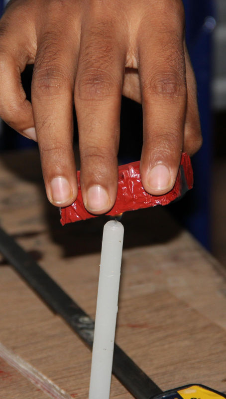
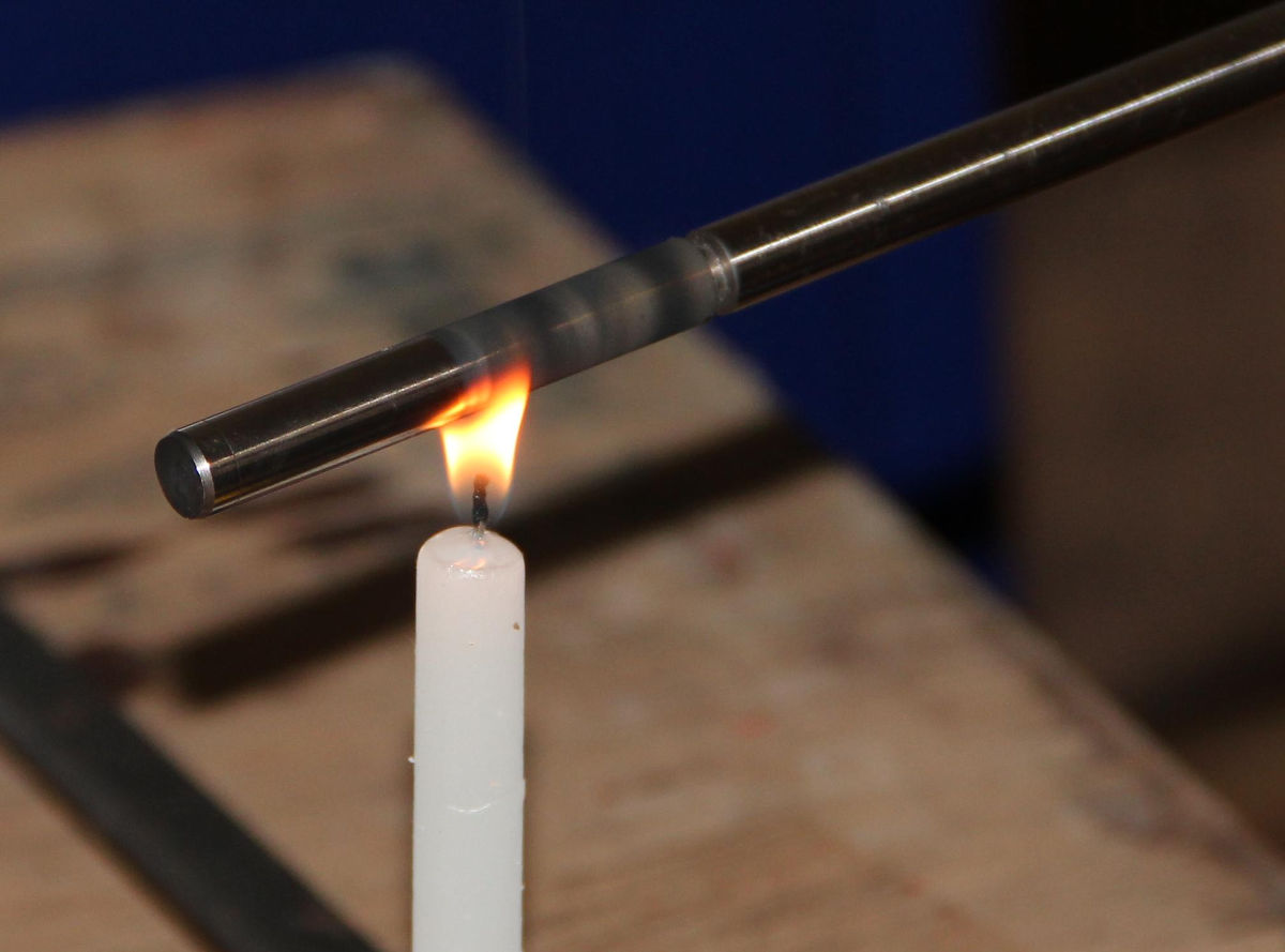
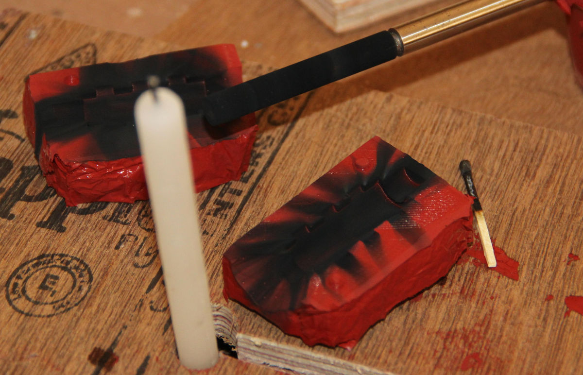
I'll be using the high temperature silicone to make the mould for the babbitt metal. This will be casted with the m8 steel rod inside. The steel rod will be coated with fairly thick layer of carbon soot from a candle flame. This soot should prevent the babbitt metal from sticking with the steel rod, acts like a release agent.
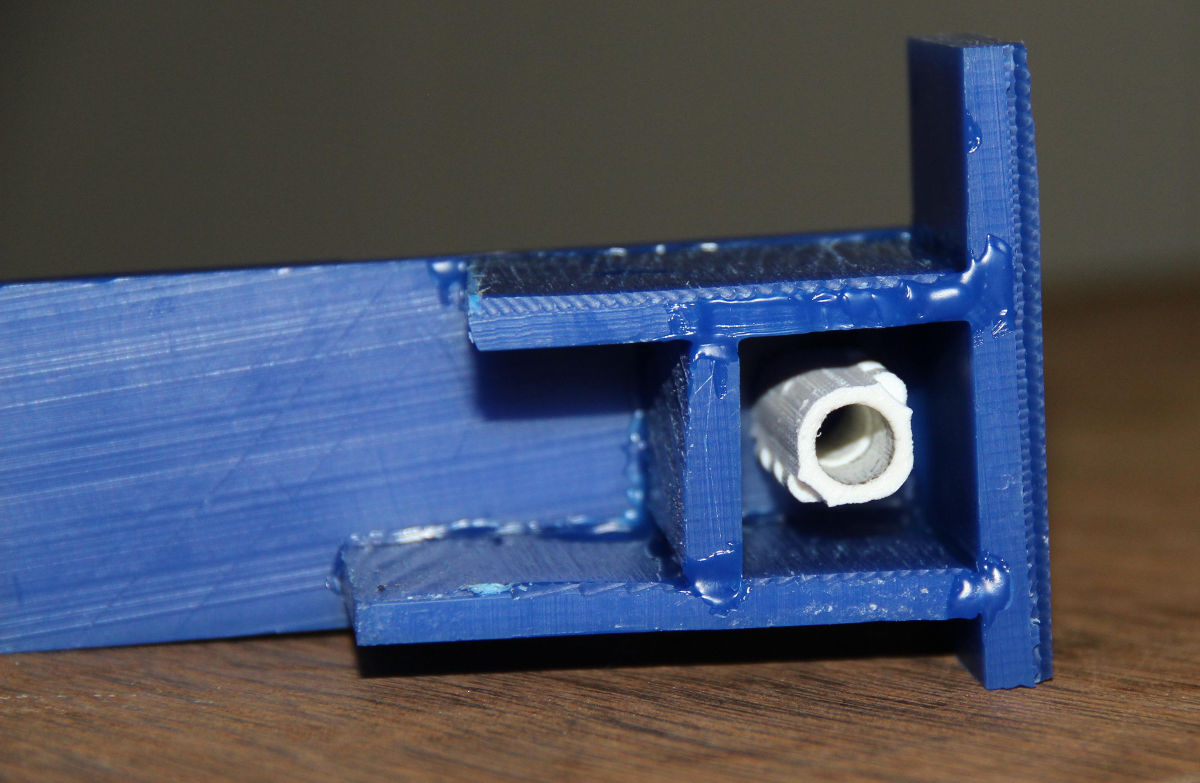
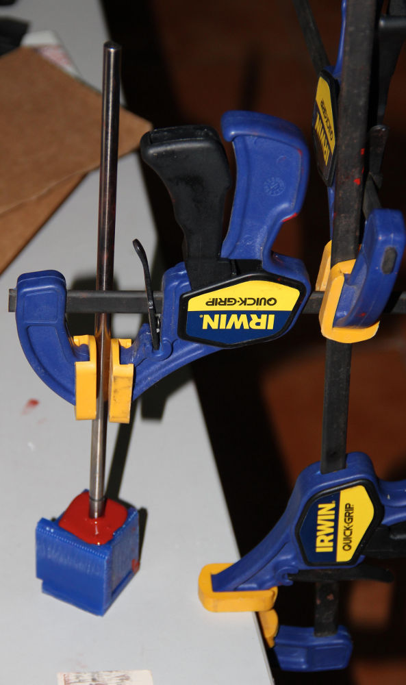
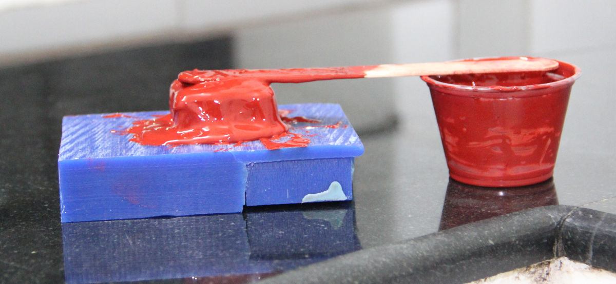
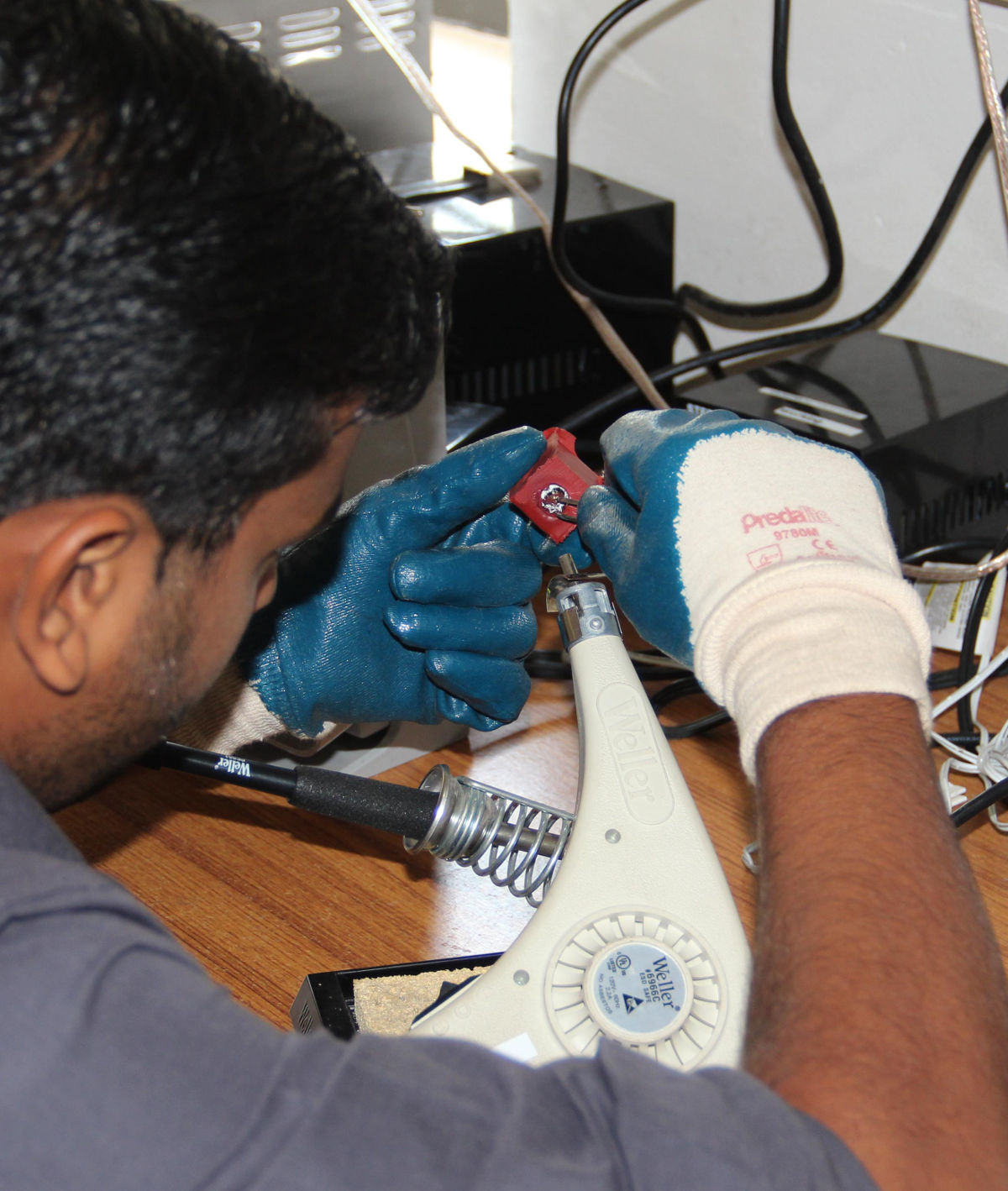
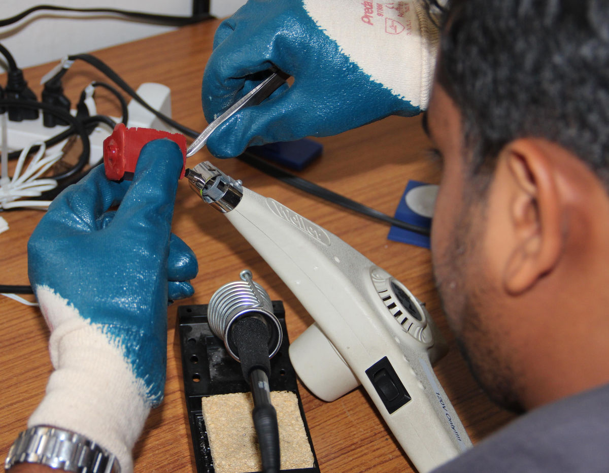
Next day, once the silicone is set (this silicone sets very quick, in just few hours), I had to remove the the plastic part inside, I could have cut it open, but it will remove the
silicone ring inside. So I decided to heat the PLA part inside to soften/melt it and remove it with the help of tweezers.
M8-slide-babbitt by sibu on Sketchfab
M8-slide-composite by sibu on Sketchfab
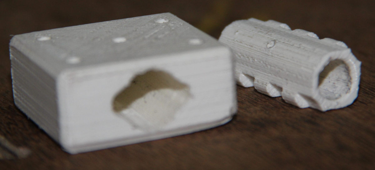
These are the designs for the new mould and you can see some pictures below.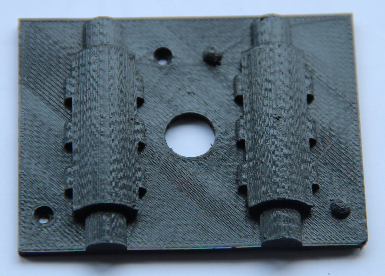
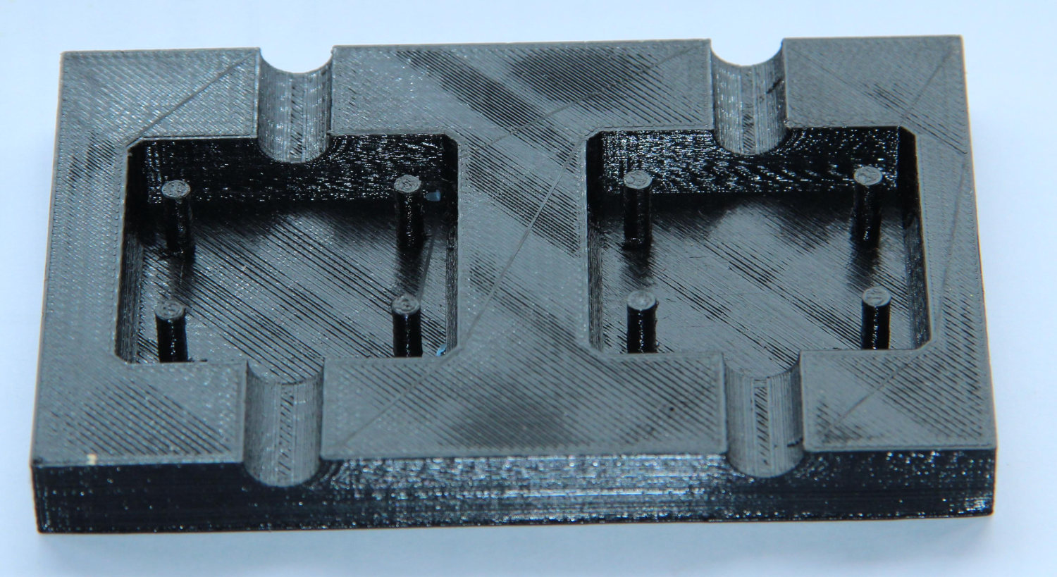
These moulds are 3D printed, to see the CNC machined moulds, go to the bottom of the page.
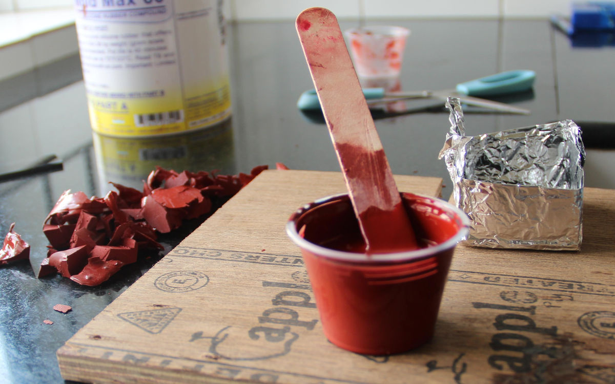
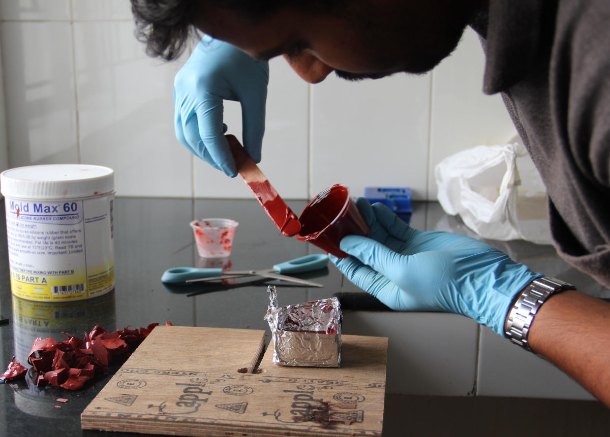
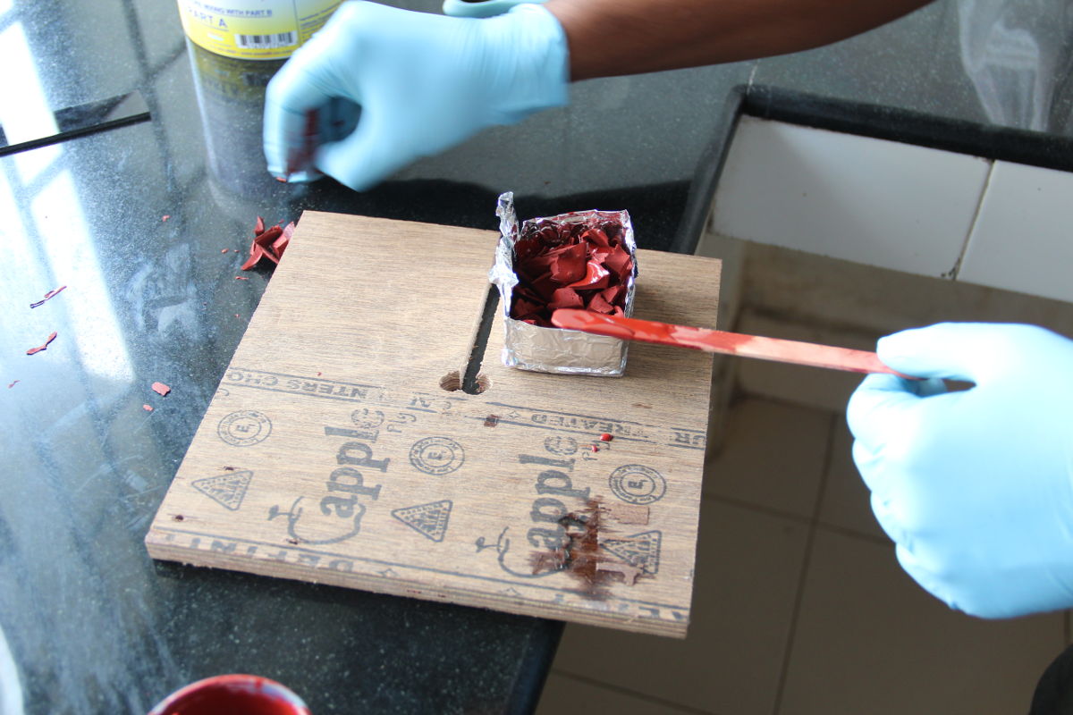
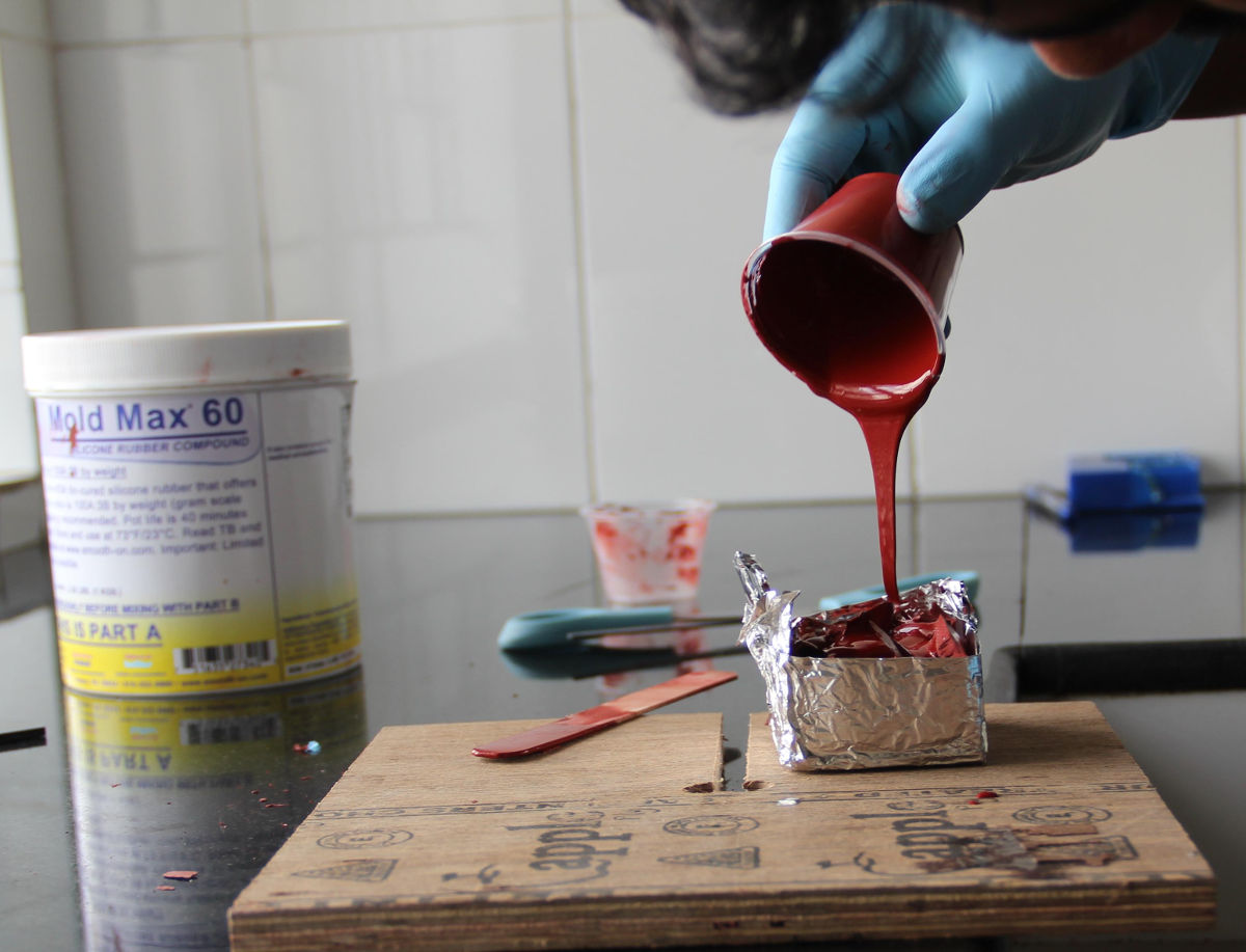
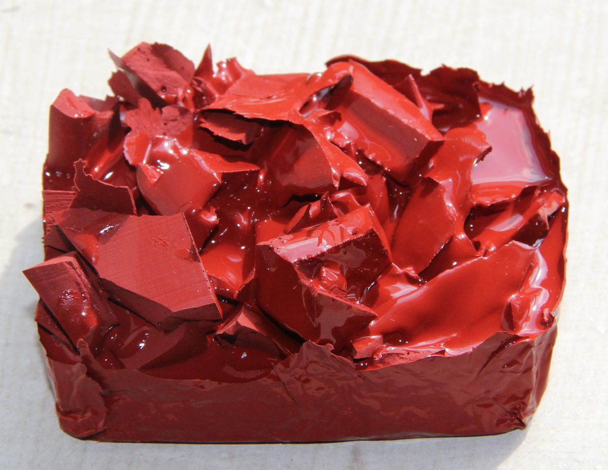
This will save a lot of new material, and is okay as the silicone sticks very well to the silicone rubber. If I were to use new silicone only, I would have to use a lot of it as the mould has to be thick.
I SHOULD HAVE SHREDDED THE SILICONE INTO MUCH SMALLER PIECES. enough to be reasonably rigid.
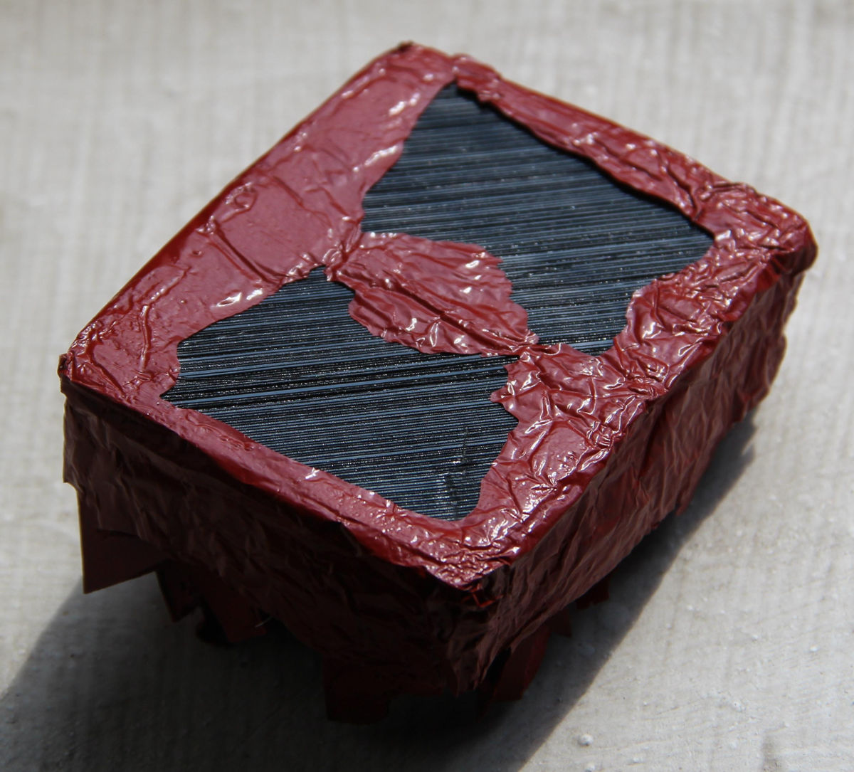
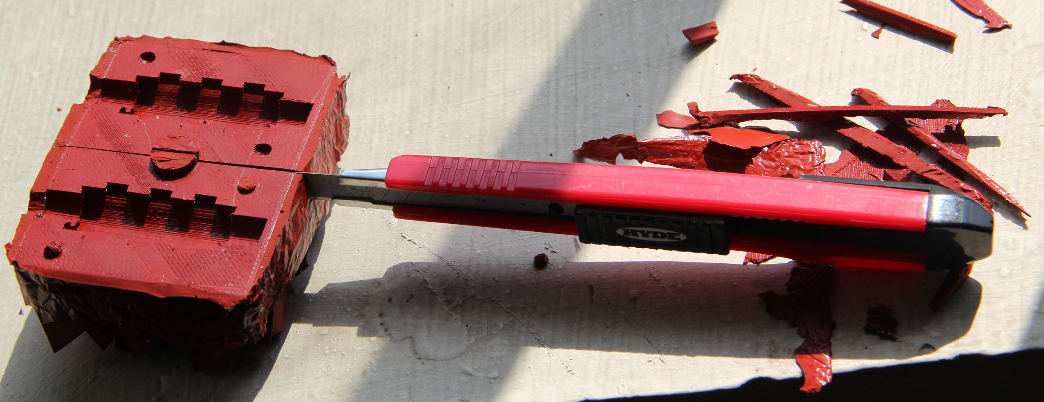
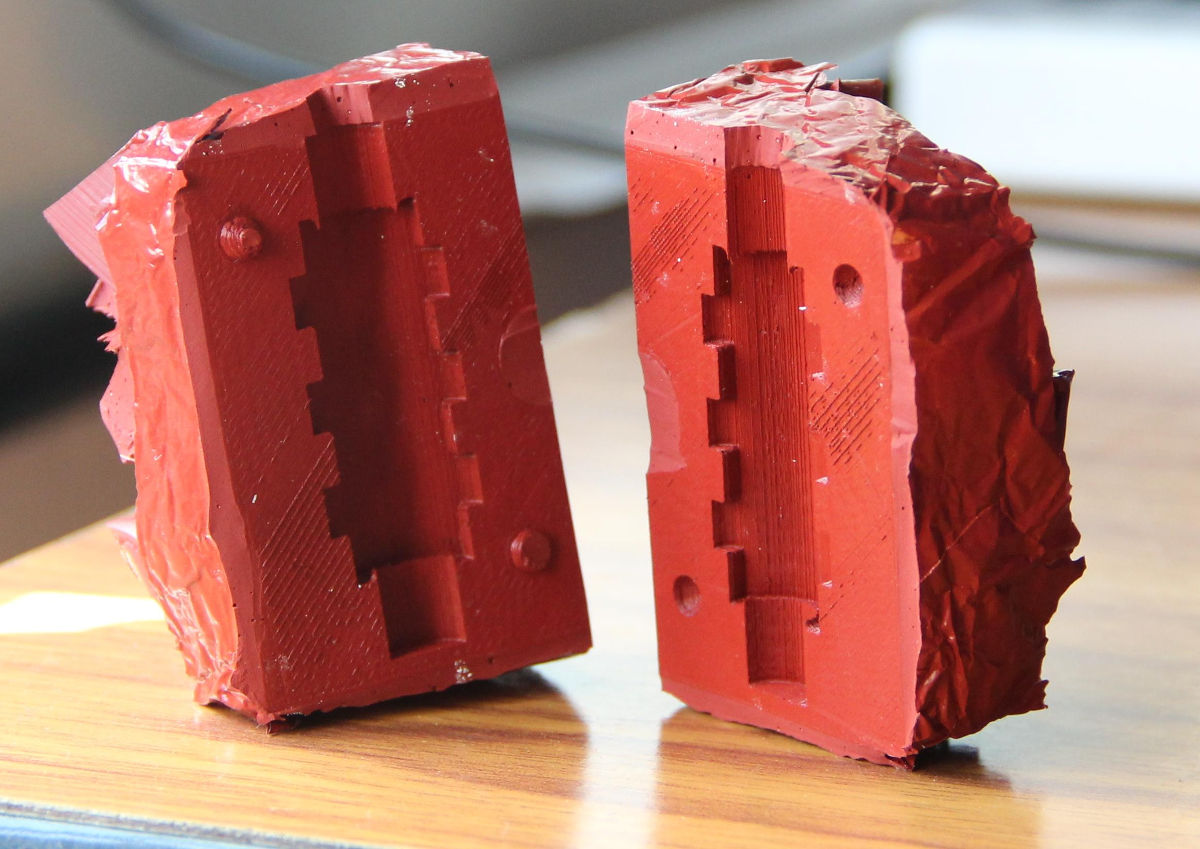
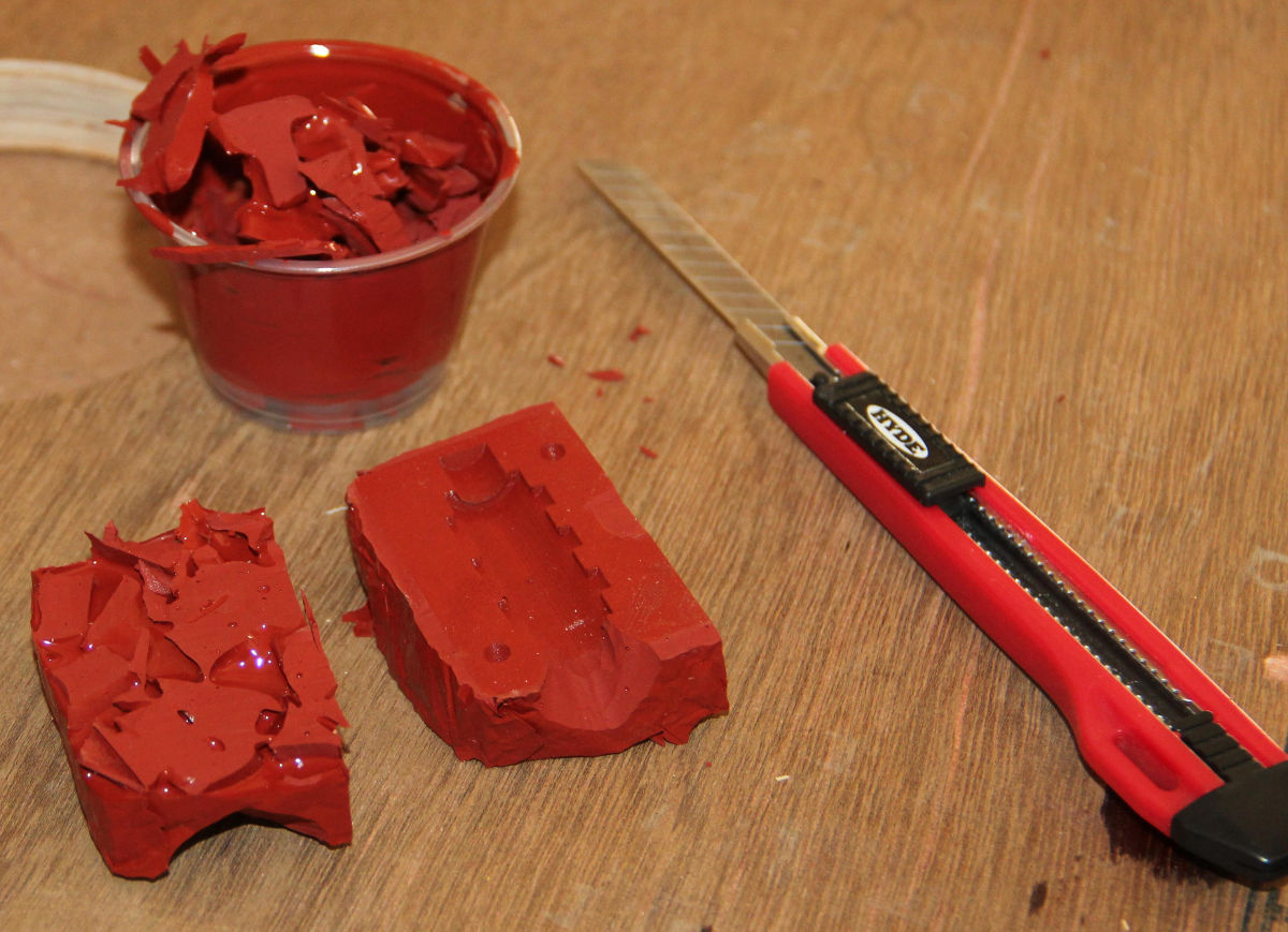
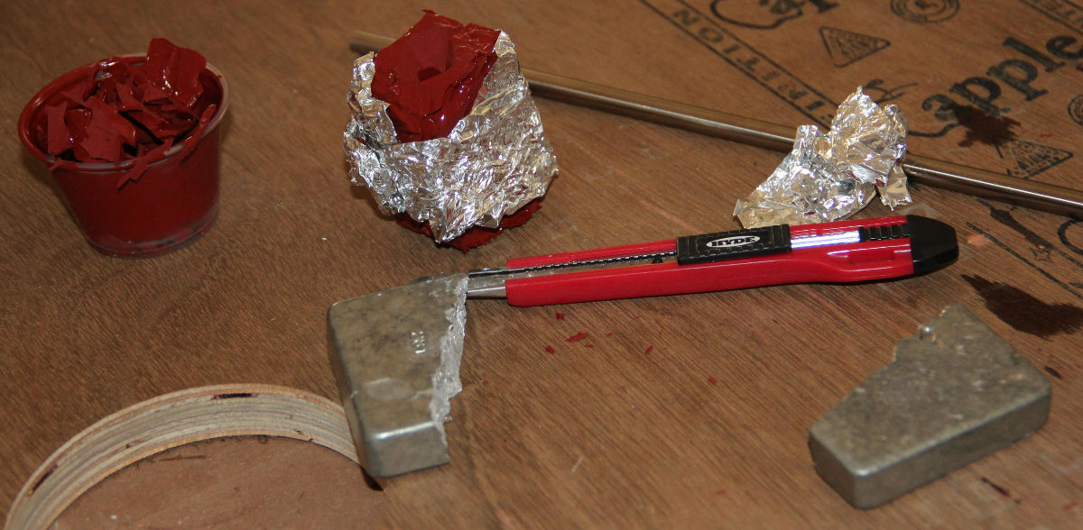
The babbitt metal is broken into pieces so that it fits into the crucible, it took only a little effort to break the metal block using hammer, the metal is brittle.
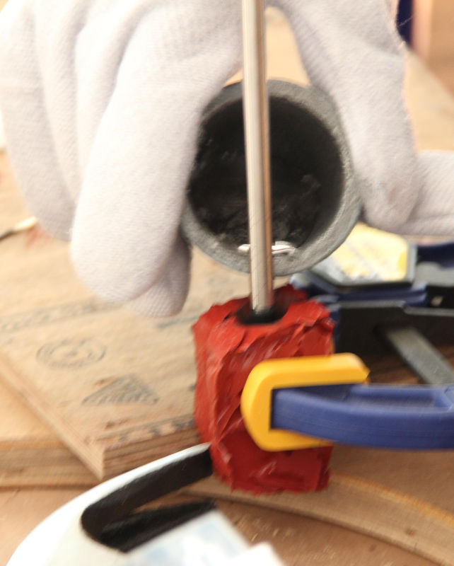
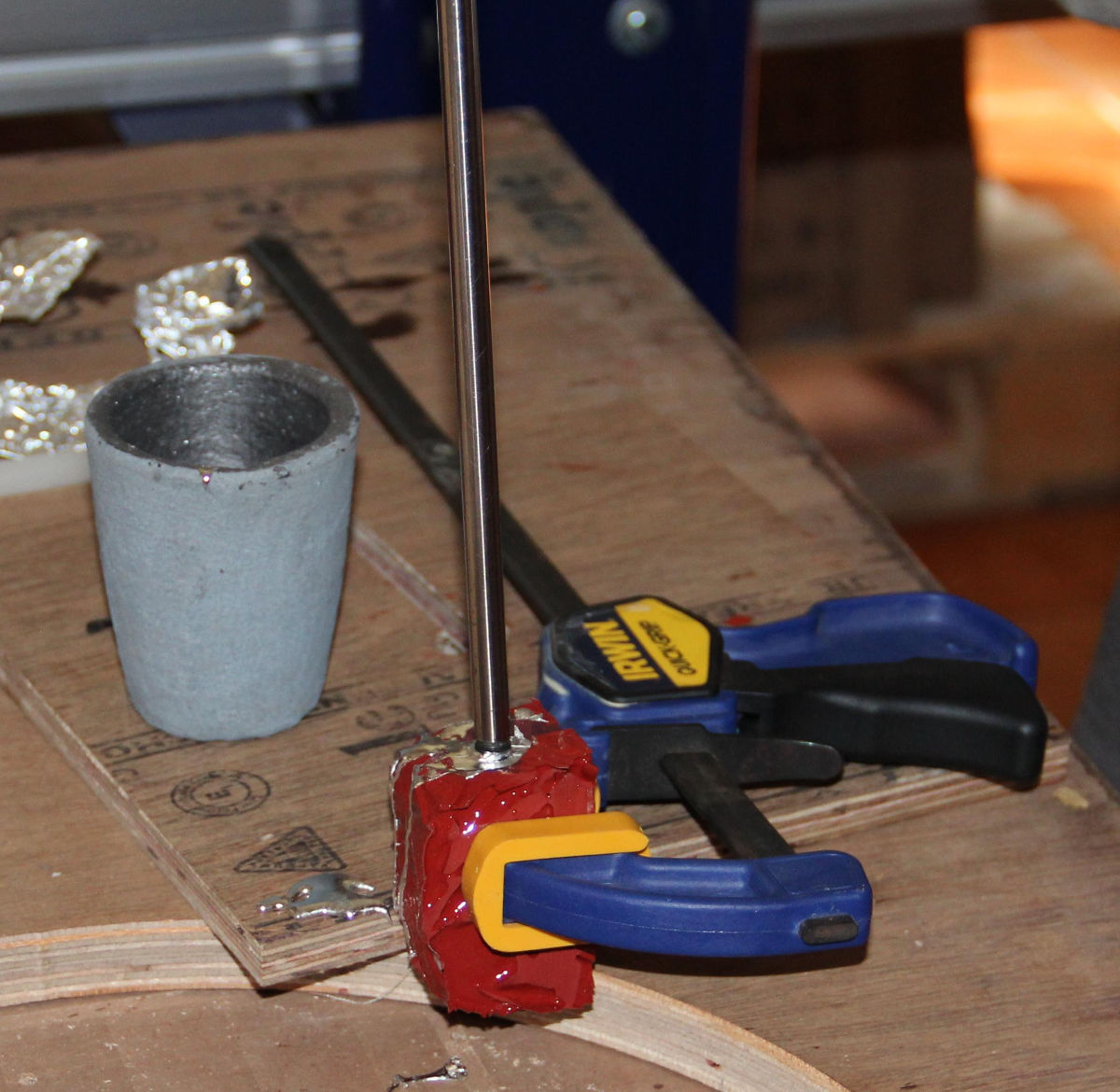
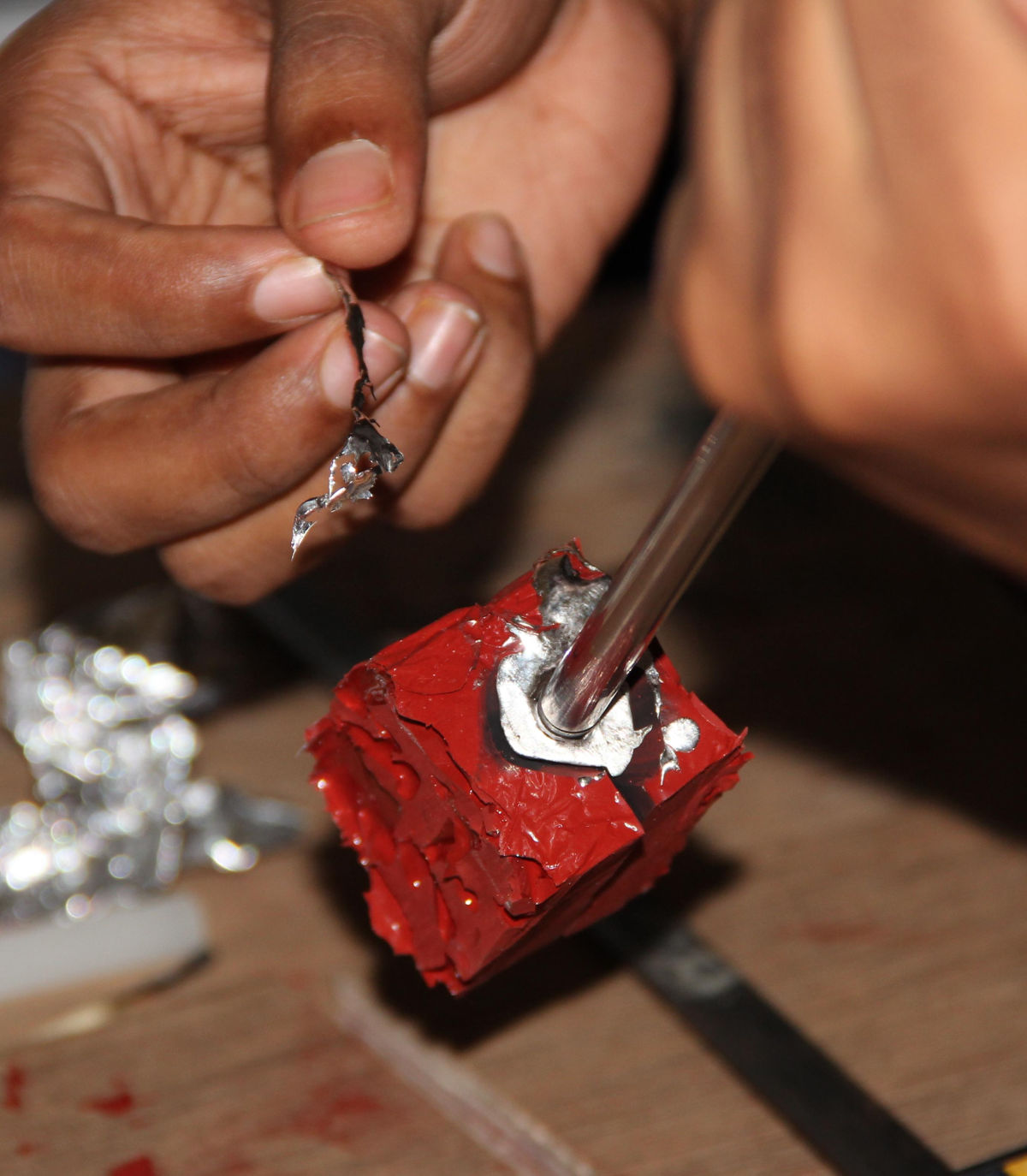
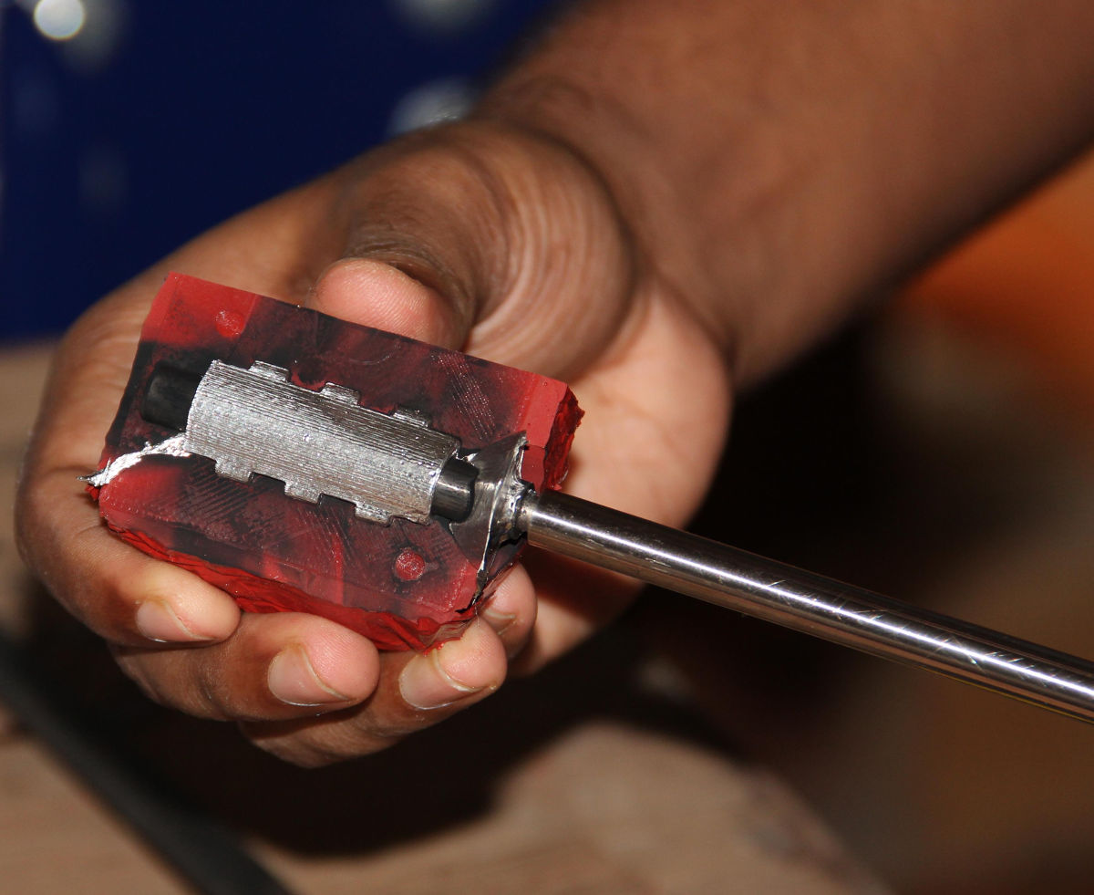

The Result of Metal Casting
The results were amazing, its extremely smooth and no instability (no wobbliness). It woks better than some of my cheap Chinese LM8UUs. Remember, these results are without any kind
of lubrication (may the carbon soot left from the casting process). But I think if I use some kind of lubrication like oil, grease or graphite powder, the results will be
even better.
AND THE BEST PART!
No noise, its silent.
Here is a video.

Final Thoughts on The Linear Bearing
Advantages
- Extremely smooth. *
- Extremely stable.
- Almost no noise.
- Can't comment on the cost, may the cost is high if you include the time invested, the material cost and the energy cost etc. But the joy you get after seeing your product working way beyond your imagination is just enough to neglect any of those expenses.
- I'm intended to use these bearings on the shafts I salvaged from the printers. These shafts are not all the same diameter, there are shafts of 8mm, 7.8mm, 8.1mm etc. Since I'm making bearings myself, I can make them to fit precisely for each rod I have.
Disadvantages
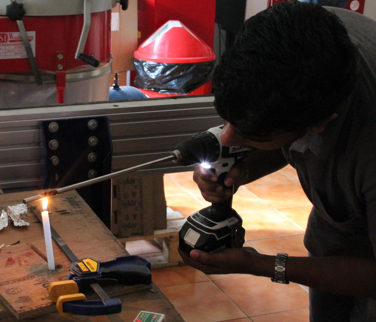
So far I found only one problem, sometimes, when the bearing is cold, like <25℃, the bearing is not so smooth anymore, the material shrinks, and the inner diameter of the bearing gets reduced. The solution could be to do the casting at a higher temperature, and maintaining the temperature till the babbitt solidifies. This will make the Babbitt harden around an expanded shaft. Another solution could be to use a thicker coating of the soot, but this will not be repeatable and reliable. Yet another solution is to put the shaft inside and connect it to a drill and let the wear and tear does the work.
Using the Modela to Make the Mould in the Machinable Wax
Though I designed and made the mould myself and used it to successfully cast parts, our instructor, Franc, said that it might be invalid as I didn't use Modela to mill the mould in wax. I actually agree with him, the purpose of each assignment is to learn something new, explore the unexplored. For making the mould I used 3D printing, I know about the process quite well, what else to say, I even made a 3D-printer for me. The task could be done using 3D printing, but then I won't be learning anything new.
The fact is that I didn't knew how to mill something in modela, so I took a shortcut, the focus was only on the end result, not the method. Thanks to Franc, for pushing me to use the modela to make the mould.
At first I tried the default Windows tools came with the machine, but I found these software lack the freedom, I couldn't adjust the parameters as I wish, like in fab-modules. Also, the tool was quite confusing in terms of units, I think in metric, but the software uses a mix of metric and imperial units, and I got frustrated and left it immediately, rebooted to my Arch Linux system and started fab modules.
First I redesigned the mould slightly with more keys for accurate positioning of the two halves.
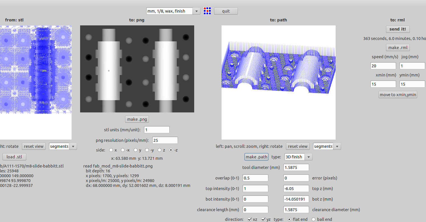
The milling process with fab-modules is almost similar to all other processes, choose the correct options (stl to mdx-20 rml in this case), set the origin, set the tool parameters and go.
For 3D milling the interface is struggling a little bit if I load .stl with fine details, when I used mesh size of 0.01 mm the software will run out of memory,
will freeze the system and eventually get terminated or crashes.
So I exported stl with (from rhino) .1 or .05 mm mesh size which worked fine.
Another problem I had was with the orientation of the stl, I had my model upside down and hence the height map(generated by the make .png option) was not getting generated (or showing
only the flat bottom of the model). So I had to choose -z option from the choice of the sides. Rest of the settings was left default.
For the tool I choose 1/8" flat bottom for roughing, an error pixel value of 0.5 for better precision. After this I set the origin and started milling.
And I strted the milling process.
Milling
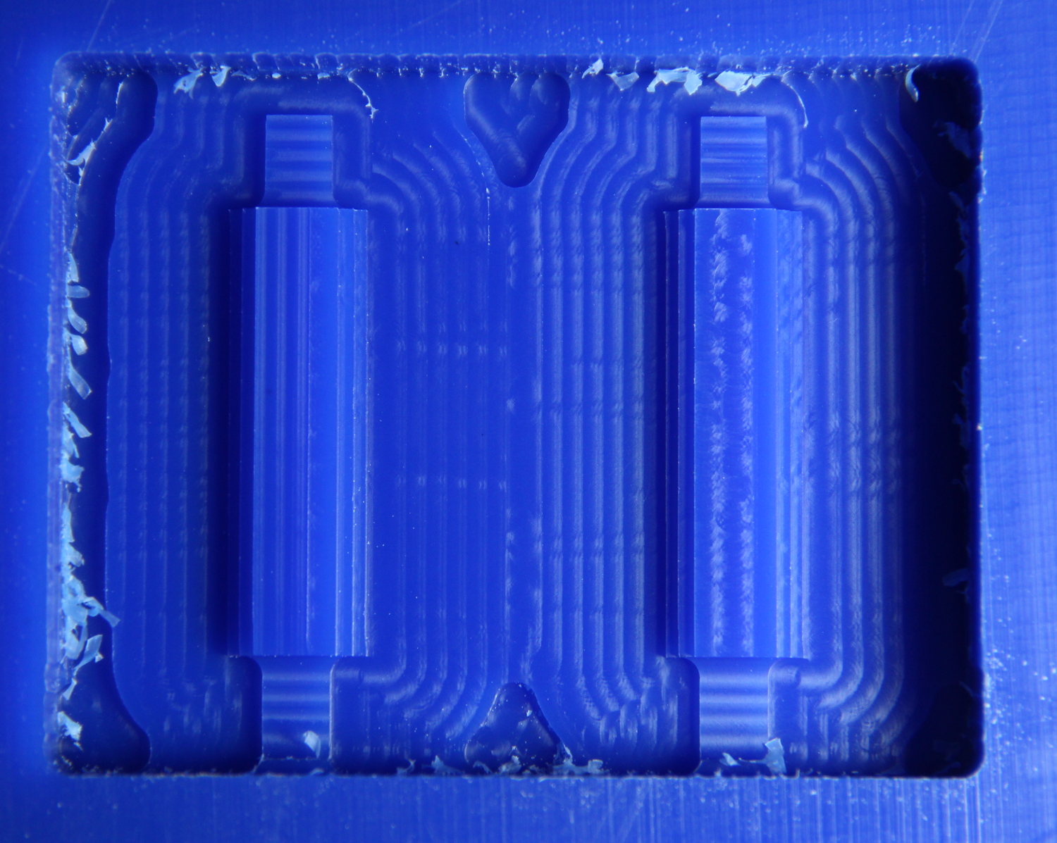
After a while, I noticed that the model is getting milled very close to the surface, not deep enough for a mould, so I had to increase (increase the magnitude, decrease
the value as the value is negative) the top and bottom z. But I can't just change it, because it just plunge into the wax by the extra mm's I'm specifying and it might break
the bit. So I started to decrease the parameters top z (mm) and bot z (mm) at steps of 1.5 mm to a final top z value
of -6 mm. Between each change in z values I will stop the job and put the new values and start the process all over again keeping the same X-Y origin.
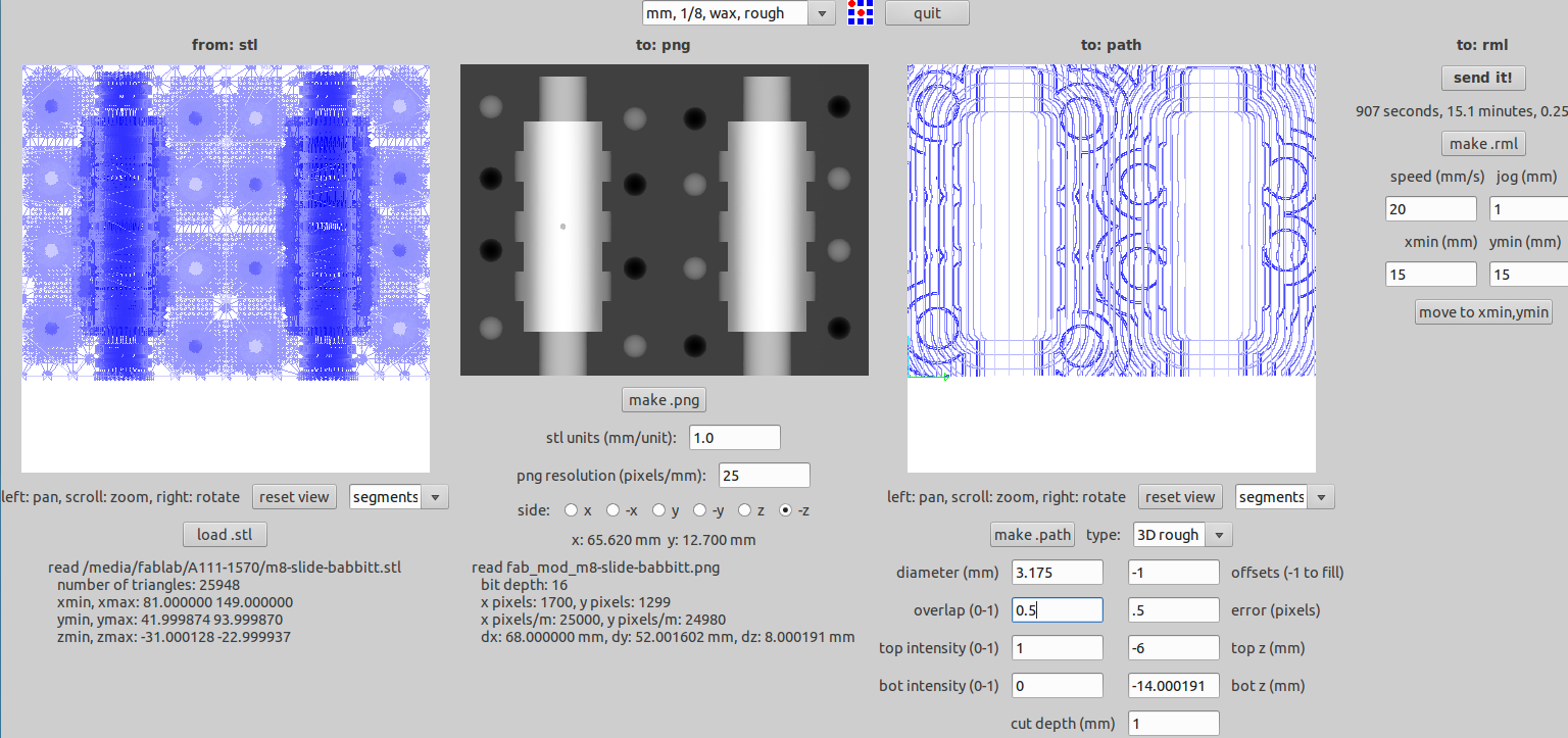
Also I didn't wait for the entire rouging process to complete, just waited for the top layer to complete and then proceeded with the next values.
But clearly this is not the way to do it, I should have made some structure taller than my model in the original stl, then this problem would never arise.
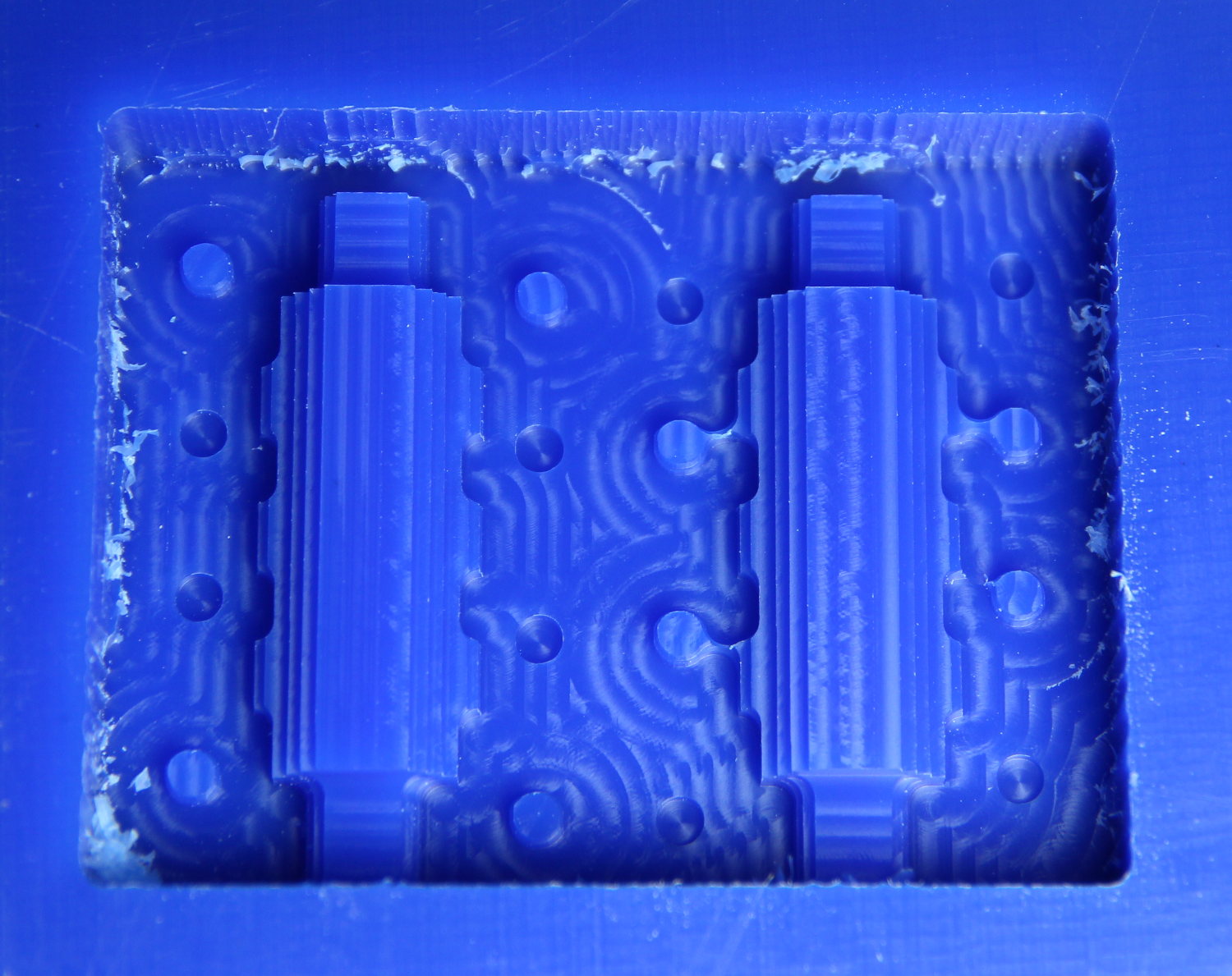
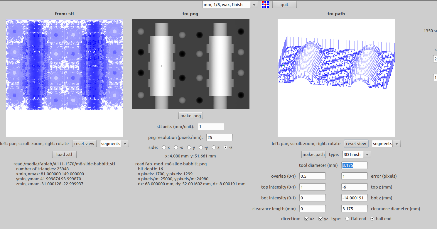
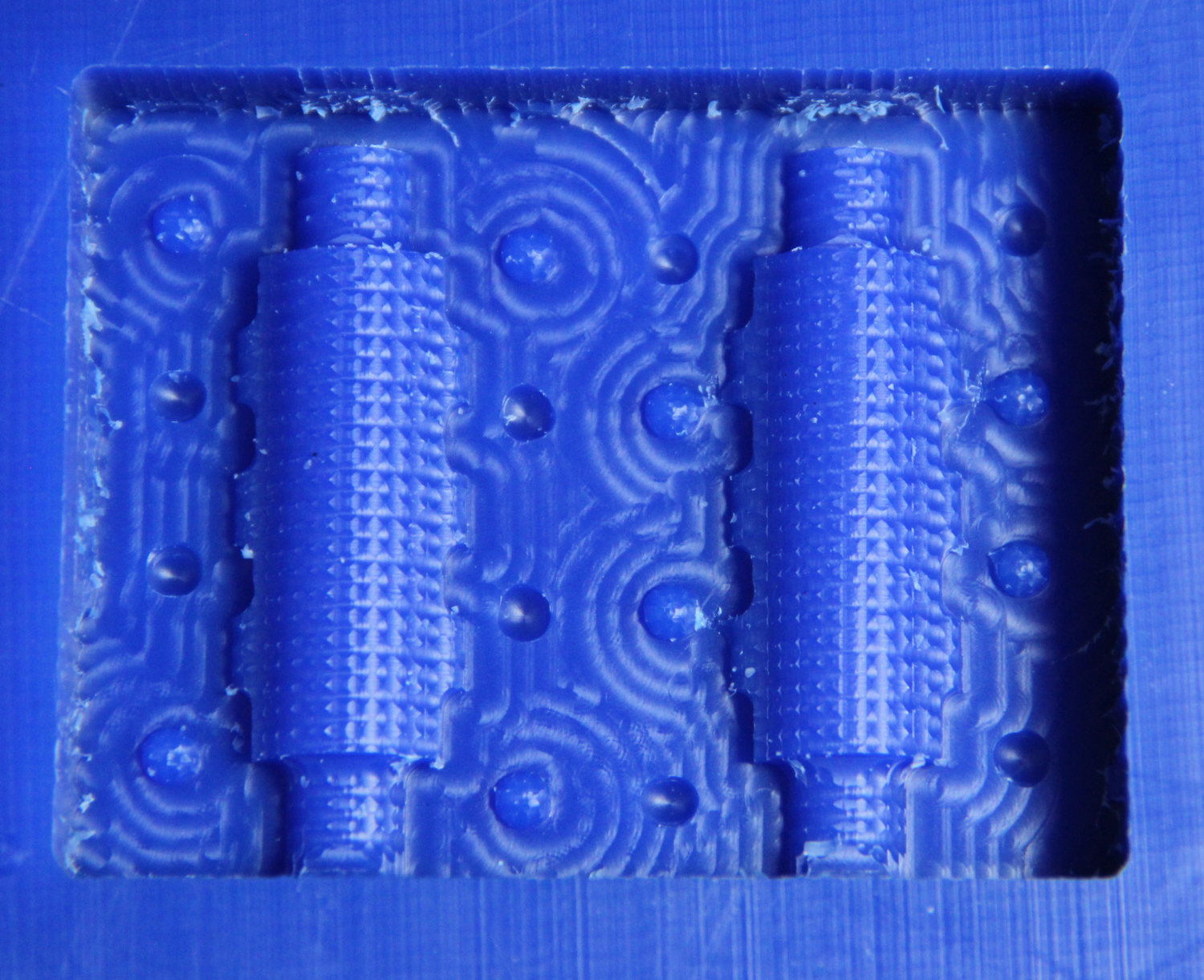
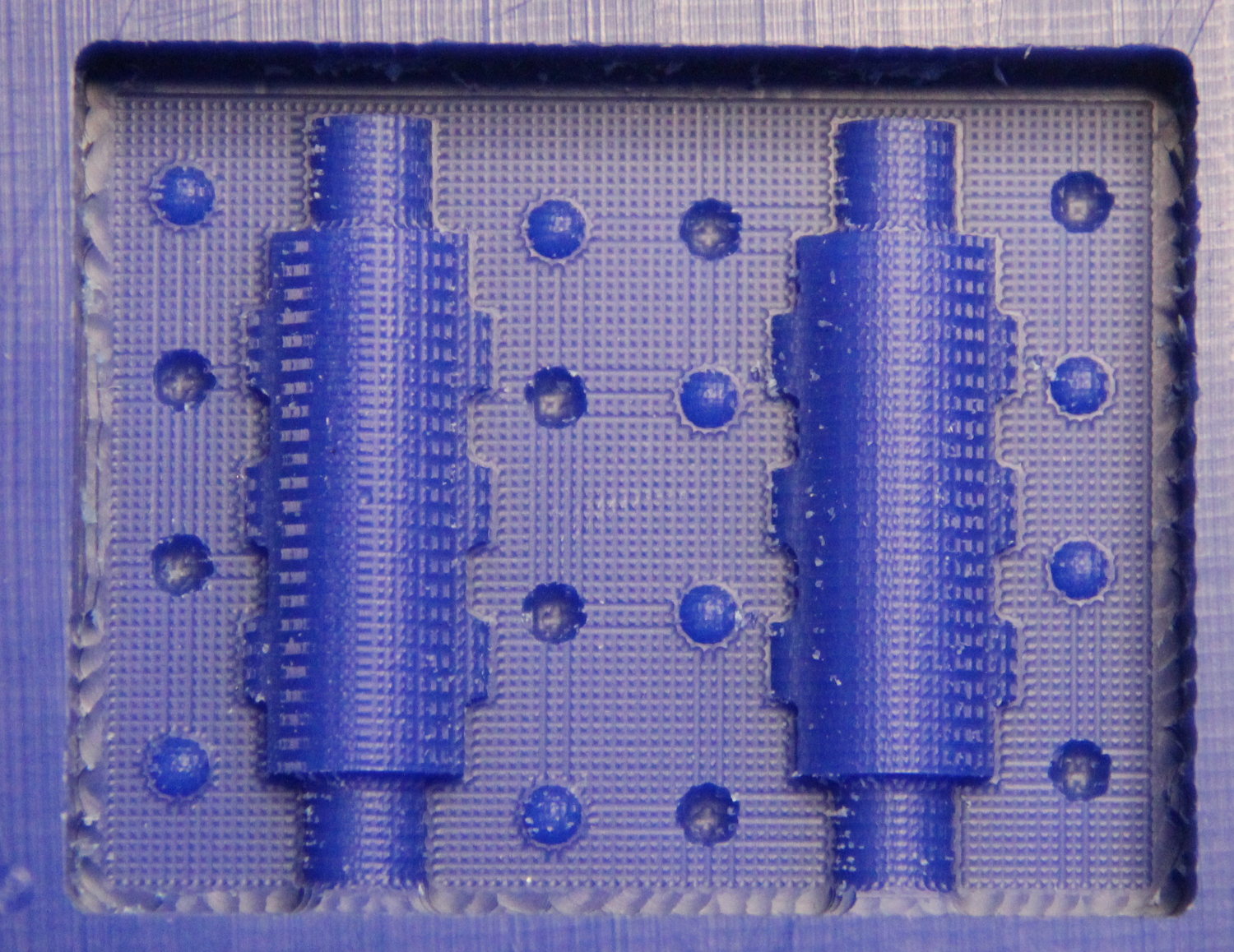
As you can see, the roughing process milled away most of the material, and the tool path was actually like a contour plot. The finish cut gave the final shape to the crude
model made by the rough cut, and the tool path was like a grid along XY plane. It is clear from the two snapshots above.
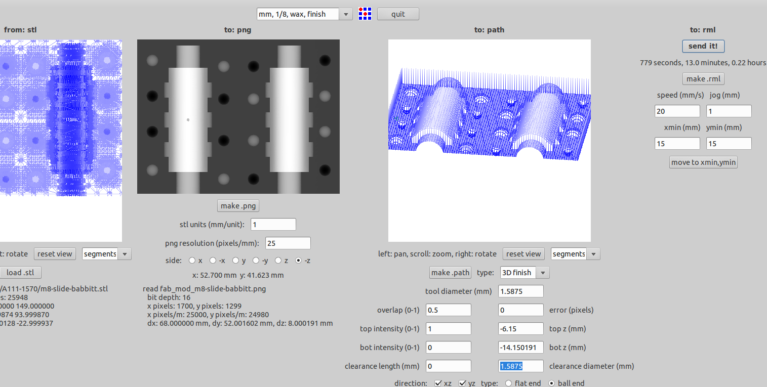
Now we have an almost finalized shape, but not exactly what we need, for that we need finer details and we need to move on to 1/16" bit. But there is no tool choice.
But the that's the beauty of the fab-module, you can 'hack' it, you can just put the correct diameter of the tool, here you have to give 1.5875 as the tool diameter and the clearance, and off you go.
