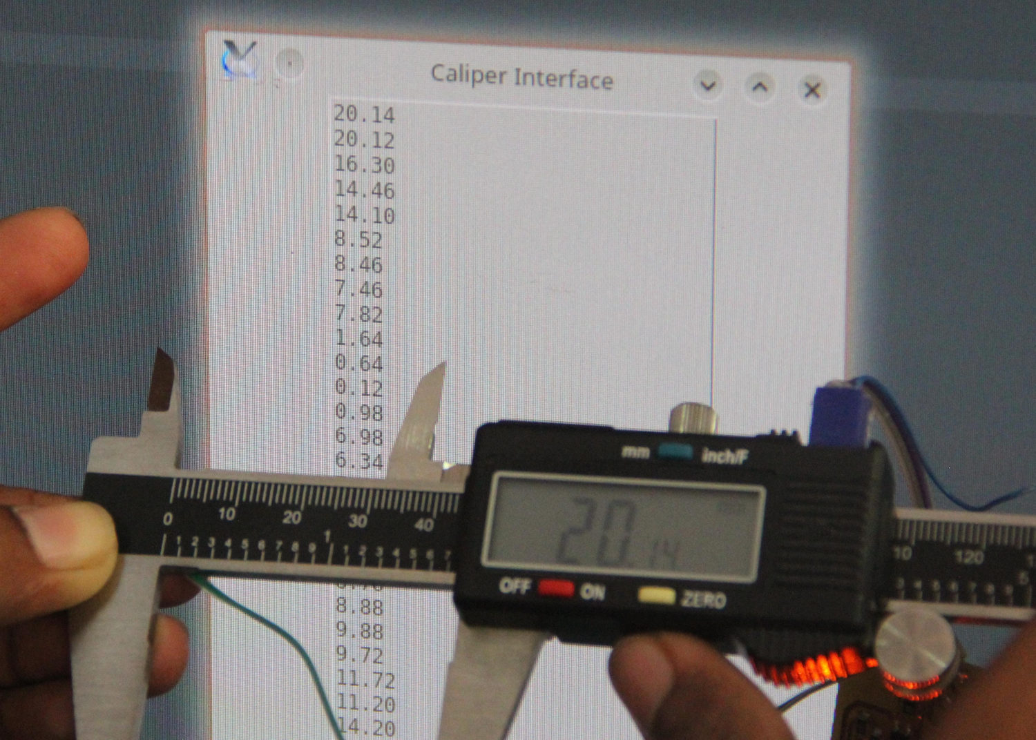
An Interface for the Digital Caliper.
While playing around with the digital caliper, I found a 'secret', 4-pin port on the device. I was expecting it to be some kind of programming or data out port.
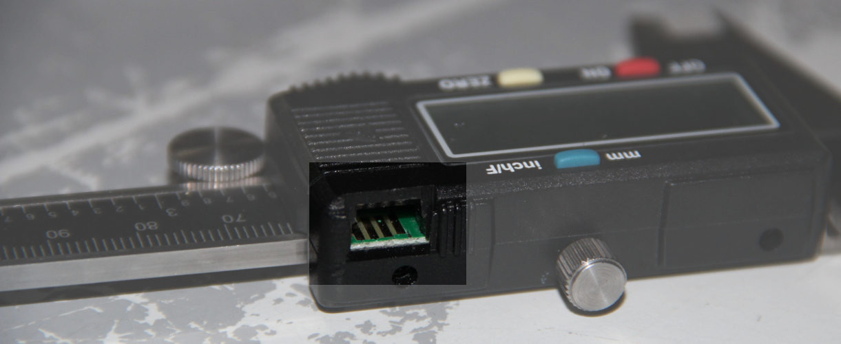
I'm going to try to make an interface to get the data from the caliper and interpret the bit stream to the real value. The micro-controller board I'll be making could be sending the
data directly to a phone or computer via serial/bluetooth/wi-fi/2.4GHz NRF2L01. A computer/android software will be written to show the values, which will be the 'interface
programming assignment'.
For the communication part I will be using soft serial, as the Tiny44 doesn't support it natively.
The Interface Data Protocol
Before I proceed further I need to know if I can get any data out of it and even if I get, whether I'll be able to interpret it, because chances are there that the device could be communicating
with some proprietary protocols.
So I started browsing again and found that many Chinese calipers are using a couple of common protocols. By the looks of it and the way the brand-name 'Neiko' sounds, the
digital caliper we have belongs to the 'Chinese caliper family'. I got confidence now!,
let's move on.
On further reading I found that the caliper's pins are vcc(+1.5v as it is powered from a button cell), DATA, CLOCK and GND.


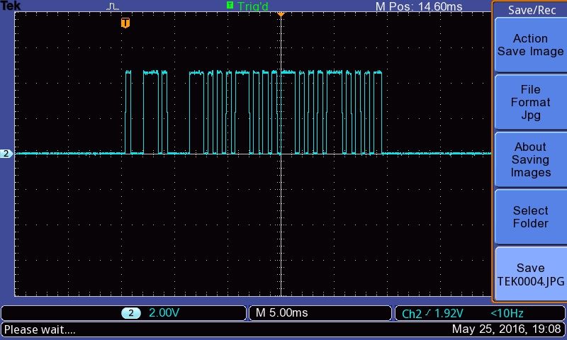
1.5v pulses from the caliper to 5v pulses so that we can feed it to the AVR chip.
The details of the Schmitt-Trigger is explained further down.
On further analysis I found that this pattern is identical to what this guy had here. So I can now interpret the data, we have to consider
- First 16-bits only, for the unsigned value.
- The bits are in reverse, 1st bit in the data stream corresponds to the least significant bit.
- Also the the bits are inverted, high pulse corresponds to 0, and low corresponds to 1.
- 20th bit for sign.
Here are some pictures explaining the interpretation.
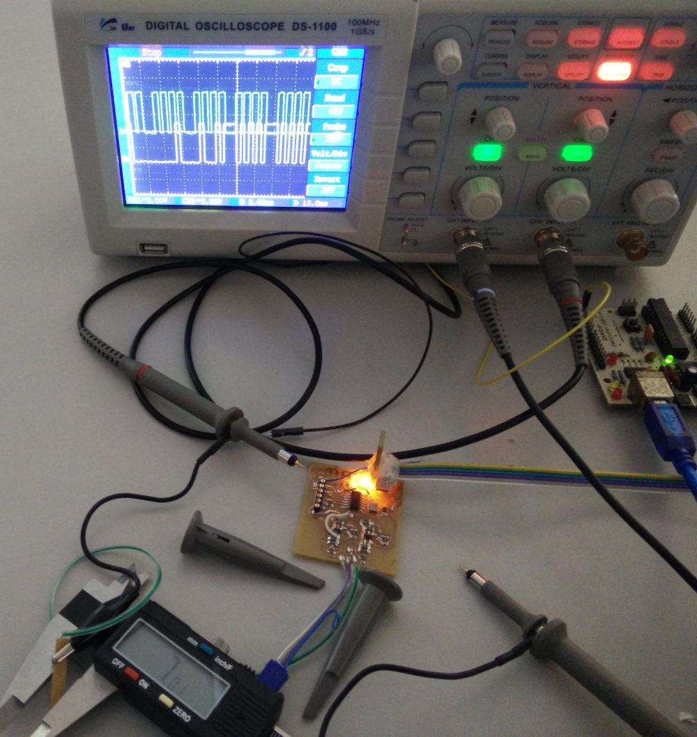
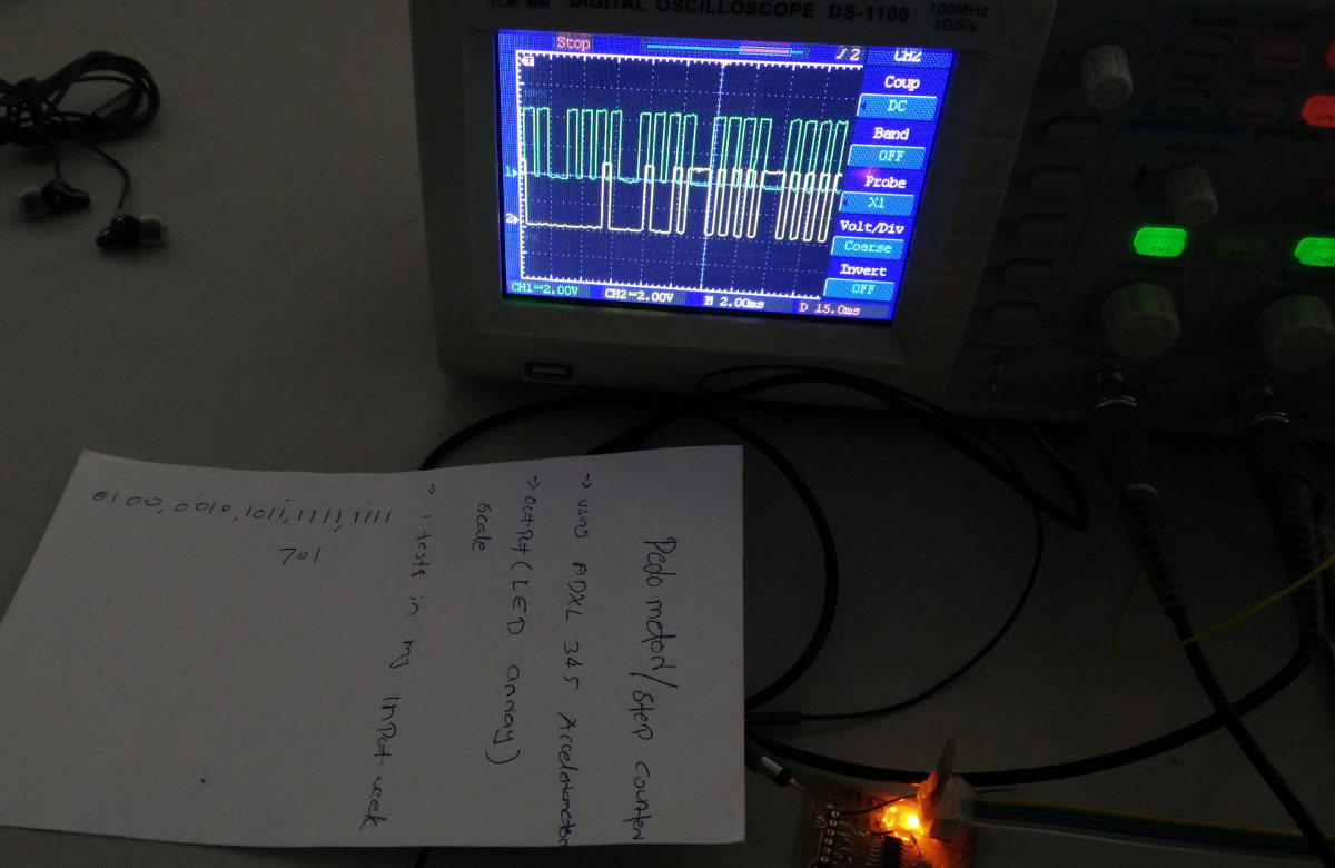
0100, 0010, 1011, 1111, 1111....1111, 1101, 0100, 0010
Inverting them (1's compliment)
0000, 0010, 1011, 1101
Now
(0000001010111101)2 = (701)10
Which is the same as the caliper reading except for the decimal point.
Board Design
So the setup is going to
- Have two Schmitt-Trigger based logic level converters, for
ClockandData. - The
Clockwill be connected toINT0or PB2. - Use the clock as an interrupt which will trigger on falling edge, the interpret vector will read the data.
- Since there is a long delay between the packets(not between the bits of a single packet), we can setup a timer which counts the time since the last interpret (last clock) and if it is more than a particular we will start processing a new packet.
- If the new value is different from last, we will sent it via serial/bluetooth/wi-fi etc.
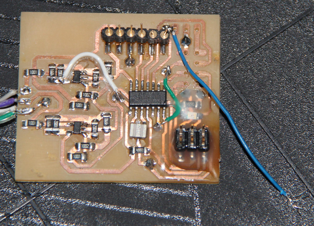
Here is the circuit diagram I designed for this assignment,
it has the following features.
- Two Schmitt-Triggers as logic level converters, convert
1.5vlogic to 5v logic for the micro-controller. - AtTiny44 with 20MHz resonator as the main micro-controller.
- FTDI header for serial communication (software serial has to be implemented as the tiny44 does not come with hardwares necessary), and an ISP header for programming, for what else used an ISP so far?
- Provision for connecting serial wireless communication module such as bluetooth, wi-fi or NRF2L01.
- Provision for adding a 3.3v DC-DC module for the wireless module as most of them uses 3.3v supply.

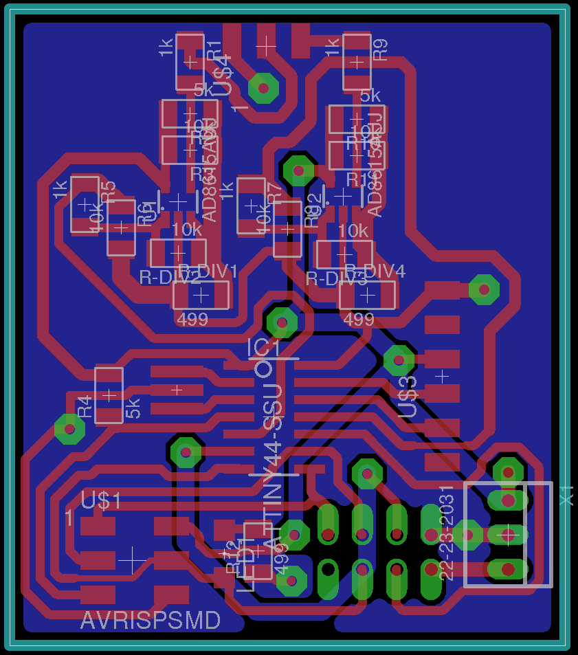
EAGLE Files are here
Board Schematic
Schmitt Trigger
This is an interesting design using an Op-Amp. We could just use a transistor as a logic level converter, but this is not ideal as they may respond to the noise too. The Schmitt-Trigger
has two thresholds an upper threshold and a lower one. The Schmitt Trigger goes high/maximum voltage when it encounters an input above the upper threshold, and stays there
even if the noise or some unintended fluctuation brings it down below this value. The value goes low/minimum voltage only when the input goes below the lower threshold.
So if we set high and low thresholds as .9v and .1v respectively, for a 1v logic pulse, and a supply voltage of 5v, the output will become high only when it detects an
input greater than .9v and remains high as long as the input doesn't fall below .1v. Now, once it falls below .1v, the output goes to zero and stays there till it gets an
input greater than .9v. This is a neat way to clean some noise, also the Op-Amp provides high input impedance.
Here is an online calculator I used to calculate the values of the resistors used with the op-amp,
AD-8615 to configure it as a Schmitt-Trigger. The calculator is an
hyperphysics.phy-astr.gsu.edu page on Schmitt-Trigger.
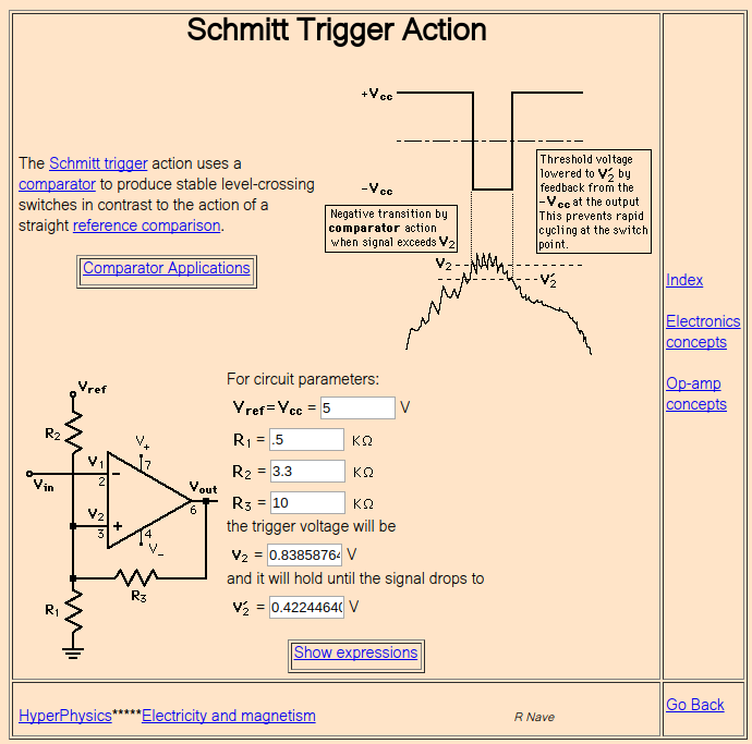
1.5v cell, I had assumed that the logic level/ logic high would be at 1.5v. But I was wrong, Its only about 1v.
May be the cell is weak, but the caliper is working and the logic levels are 1v and 0v. So I had to change the Schmitt-Trigger design from the initial design for 1.5v logic pulse, I had to change the resistor, R1 from 1KΩ to 0.5KΩ.
Connector
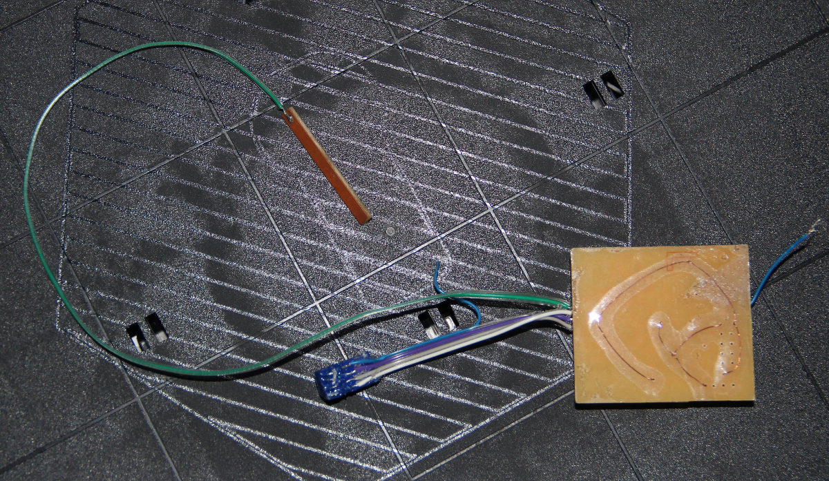
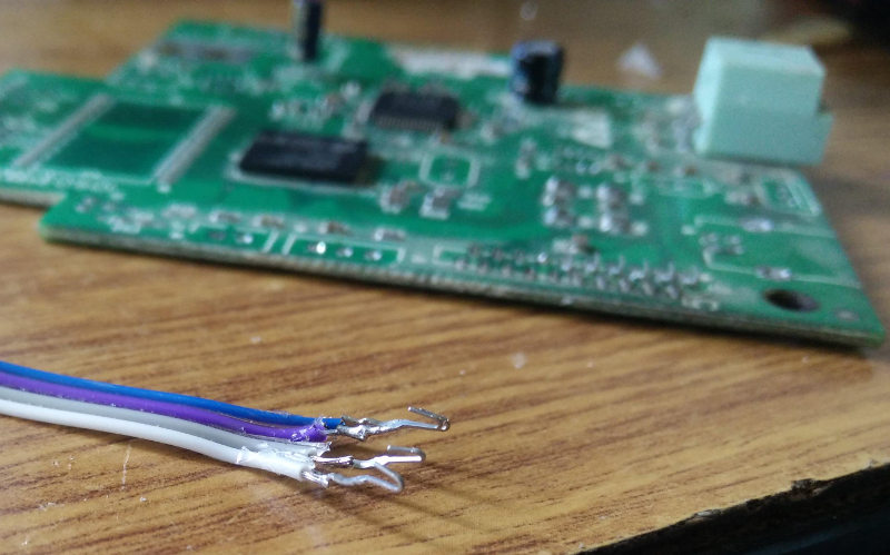
It's not a good idea to solder wires to the caliper, so I decided to make a connector.
First I tried making a connector using PCB. thickened at the contacts using the solder. This fits nicely but the contacts are not even/flat and hence not all the terminals
make contact at the same time.
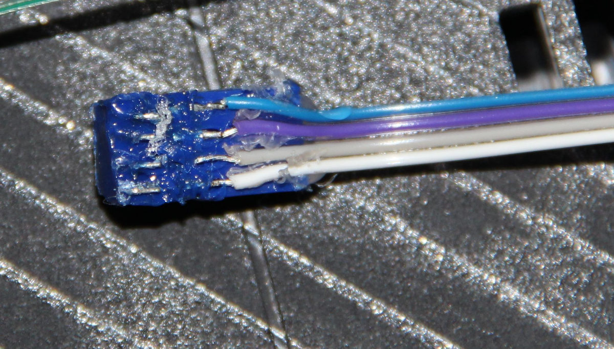
So I thought about 3D printed connectors. And found out a design from
thingiverse. So I made the print and decided to add spring contacts salvaged from the scrap ink-jet printers. The spring contacts were soldered and then buried deep
into the grooves for the connector pins.
CODE
Here is the code which interprets the data and sent it via serial communication, I used the FTDI in an Arduino UNO to get the data to the computer and used Arduino IDE's serial monitor
to display the information. The serial communication is implemented with software serial code written by Neil,
hello.ftdi.44.echo.c. I extracted the relevant parts form hos code.
The chip is operating at 20MHz and the baud rate is 115200.
#define F_CPU 20000000UL
#include <avr/io.h>
#include <stdlib.h>
#include <avr/interrupt.h>
#include <util/delay.h>
#include <avr/pgmspace.h>

#define output(directions,pin) (directions |= pin)  // set port direction for output
#define set(port,pin) (port |= pin)                 // set port pin
#define clear(port,pin) (port &= (~pin))            // clear port pin
#define pin_test(pins,pin) (pins & pin)               // test for port pin
#define bit_test(byte,bit) (byte & (1 << bit))  // test for bit set
#define bit_delay_time 8.5                            // bit delay for 115200 with overhead
#define bit_delay() _delay_us(bit_delay_time)         // RS232 bit delay
#define half_bit_delay() _delay_us(bit_delay_time/2)  // RS232 half bit delay
#define char_delay() _delay_ms(10)                    // char delay

#define serial_port PORTA
#define serial_direction DDRA
#define serial_pins PINA
#define serial_pin_in (1 << PA0)
#define serial_pin_out (1 << PA1)

#define max_buffer 8

unsigned int fin_read_h, fin_read_l, fin_read;
unsigned int  temp_read;
unsigned int last_read;
unsigned int bit_count, sign_bit;

void put_char(volatile unsigned char *port, unsigned char pin, char txchar)
{
// send character in txchar on port pin,  assumes line driver (inverts bits)
	clear(*port,pin);             // start bit
	bit_delay();
	if bit_test(txchar,0)
		set(*port,pin);
	else
		clear(*port,pin);
	bit_delay();
	if bit_test(txchar,1)
		set(*port,pin);
	else
		clear(*port,pin);
	bit_delay();
	if bit_test(txchar,2)
		set(*port,pin);
	else
		clear(*port,pin);
	bit_delay();
	if bit_test(txchar,3)
		set(*port,pin);
	else
		clear(*port,pin);
	bit_delay();
	if bit_test(txchar,4)
		set(*port,pin);
	else
		clear(*port,pin);
	bit_delay();
	if bit_test(txchar,5)
		set(*port,pin);
	else
		clear(*port,pin);
	bit_delay();
	if bit_test(txchar,6)
	  set(*port,pin);
	else
	  clear(*port,pin);
	bit_delay();
	if bit_test(txchar,7)
		set(*port,pin);
	else
		clear(*port,pin);
	bit_delay();
	set(*port,pin);               // stop bit
	bit_delay();
	//char_delay();               // char delay
	bit_delay();
}

void put_string(volatile unsigned char *port, unsigned char pin, char *str)
 {
	// print a null-terminated string
	 static int index;
	index = 0;
	do {
		put_char(port, pin, str[index]);
		++index;
	} while (str[index] != 0);
}

int main(void)
{
	static char buffer[max_buffer] = {0};
// set clock divider to /1
	CLKPR = (1 << CLKPCE);
	CLKPR = (0 << CLKPS3) | (0 << CLKPS2) | (0 << CLKPS1) | (0 << CLKPS0);

// initialize output pins
	set(serial_port, serial_pin_out);
	output(serial_direction, serial_pin_out);

	DDRB = 0b00000000;
	DDRA = 0b11001011;

	cli();				               // disable global interrupts

	// initialize Timer1 the 16bit timer
	TCCR1A = 0;
	TCCR1B = 0;
	// Use CS10, CS11 and CS12 bits for 1/64 prescaler:
	TCCR1B |= (1 << CS10)|(1 << CS11);

	//enble int0
	GIMSK |= (1<<INT0); //PCICR is GIMSK in attiny
	MCUCR = 1<<ISC01 | 0<<ISC00;	// Trigger INT0 on falling edge

	sei();			                              // enable global interrupts:

	while(1)
	{
//		if (fin_read != last_read)
		{
      put_string(&serial_port, serial_pin_out, "new value  ");
			itoa (fin_read_h, buffer, 10);
			if (sign_bit == 1)
				put_char(&serial_port, serial_pin_out, '-');		//sign
			put_string(&serial_port, serial_pin_out, buffer);
			put_char(&serial_port, serial_pin_out, '.');			//decimal point
			if (fin_read_l < 10)
				put_char(&serial_port, serial_pin_out, '0');
			itoa (fin_read_l, buffer, 10);
			put_string(&serial_port, serial_pin_out, buffer);
			put_char(&serial_port, serial_pin_out, '\"');
			put_char(&serial_port, serial_pin_out, 10);          // new line
			last_read = fin_read;
		}
	}
}

ISR(INT0_vect)
{
	PORTA ^= 0b01000000;		           	//debugging LED, check mosi pin
	if ((TCNT1 > 10000))
  {
		fin_read = temp_read;
		fin_read_h = temp_read/100;
		fin_read_l = temp_read - fin_read_h*100;
		temp_read =  0;
		bit_count = 0;
		sign_bit = 1;
	}
	else
	{
		if (bit_count < 15)
		{
			temp_read = temp_read>>1; 				// temp_read /= 2;	  //right shift
			if (~PINA & 0b00000100)
			{
				temp_read |= 32768;	            //2^15
			}
		}
		else
		{
			if (bit_count == 19 && PINA & 0b00000100) 		//20th bit corresponds to sign bit
				sign_bit = 0;
		}
		bit_count += 1;
	}
	TCNT1 = 0;
}
This program is not the perfect, need a little workaround, first of all I wanted the program to send the latest reading only if it is different from the last, else the code will sent
10 readings per second, like what it is doing right now.
Secondly, there is something wrong with my interpretation technique, the output is always ends with an even number, somehow it skips the odd number and rounds off to the
nearest even number, must be missing the least significant bit, which decided the if the final value if odd or even.

Now I need to send this data to a computer program/android app to display this value. Which will complete the interface designing assignment.
